EN
EN

When a press brake part includes a deep box, tall return flange, or several bends close together, choosing a punch based only on angle and radius can lead to interference during forming. The critical question is whether the previously formed flange has enough space to move around the punch body.
A straight punch works well when the part remains open and the flange does not enter the punch's clearance zone. A gooseneck punch becomes useful when the punch body itself would otherwise collide with an existing flange.
That makes punch selection a geometry problem as much as a tooling problem. Flange depth, return length, tool height, punch radius, die opening, tonnage, bend sequence, and machine compatibility all need to be considered before the tooling is ordered.
A straight punch is generally suitable for conventional bends where there is sufficient clearance around the upper tool.
Its simple, continuous profile makes it useful for standard 90-degree bending, open brackets, panels, shallow channels, and other parts where previously formed flanges do not approach the punch body.
MIHARTING's guide to straight and gooseneck press brake punches similarly describes straight punches as a general-purpose solution for standard bending and parts without special clearance restrictions.
For example, consider an L-shaped bracket with a relatively short flange. If the flange remains outside the punch body throughout the stroke, a straight punch may provide everything the application requires.
In this situation, choosing a gooseneck profile simply to make the tooling more specialized does not necessarily provide a practical benefit.
A straight punch is typically worth considering when:
the bend is relatively open;
the formed flange is shallow;
there is no deep return flange;
adjacent geometry does not approach the punch body;
standard punch height provides sufficient clearance;
the required bend radius can be achieved with the available tooling; and
the machine's existing tooling system supports the selected punch.
The important point is that a straight punch is not merely the "basic" option. When the geometry does not require additional clearance, it can be an efficient and technically appropriate choice.
.jpg "straight and gooseneck press brake punches")
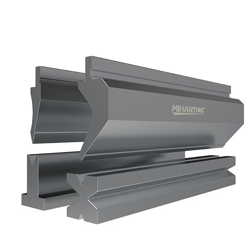
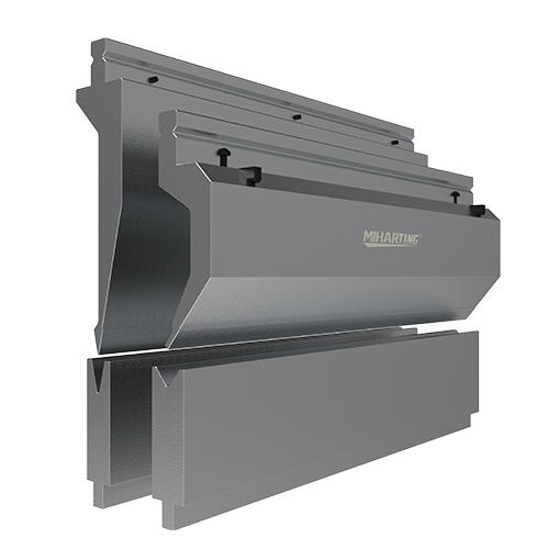
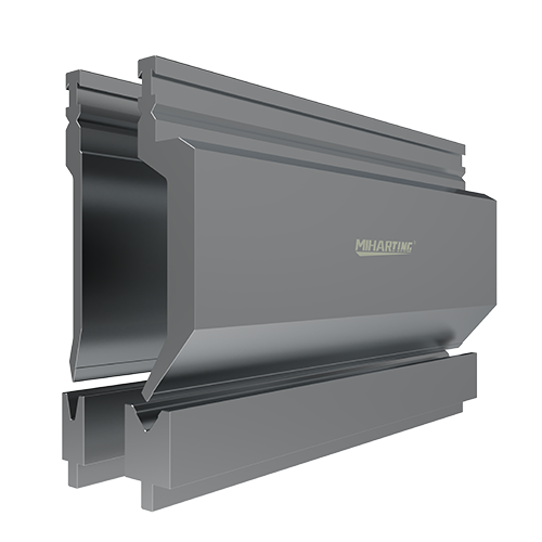
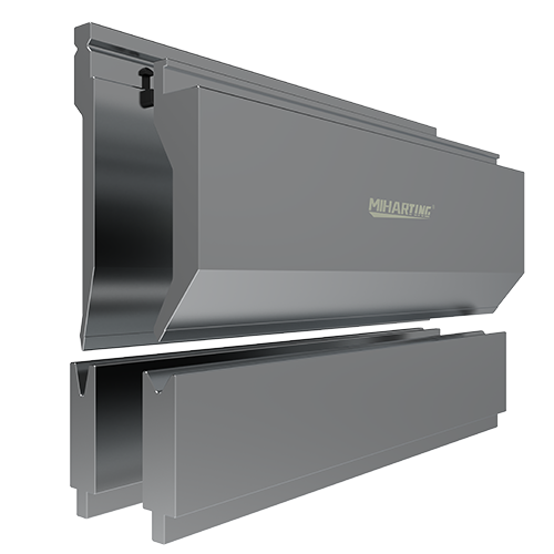
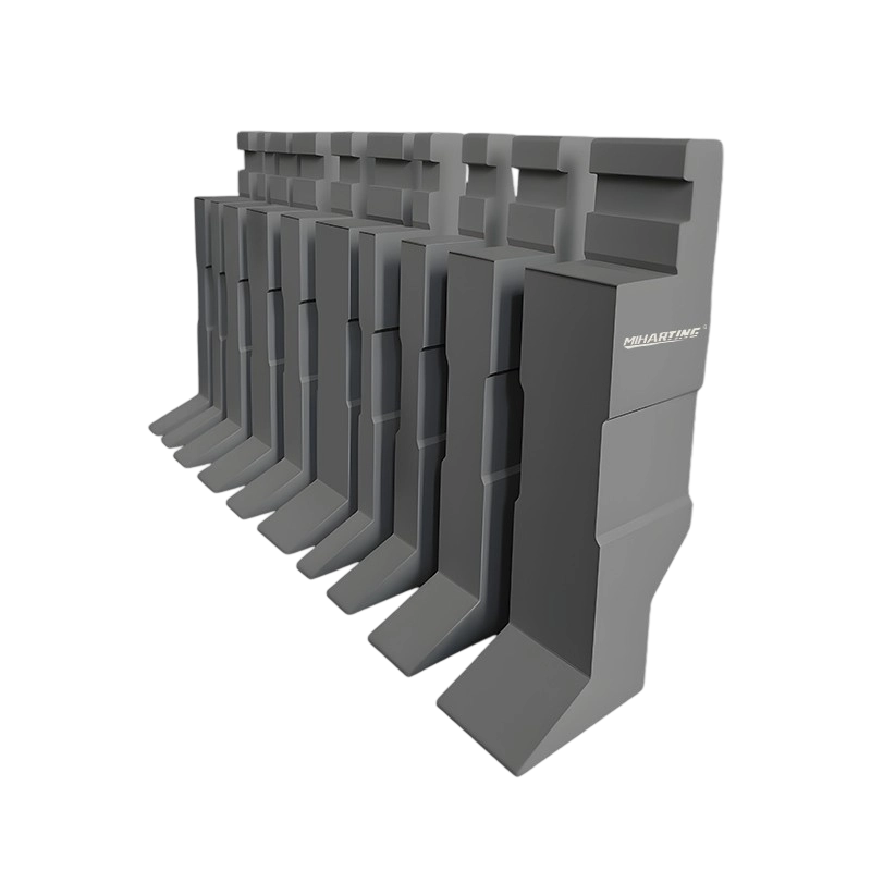
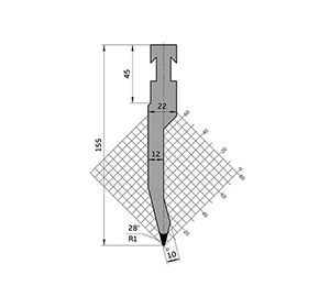
The defining feature of a gooseneck punch is the relieved or curved section behind the punch nose.
That relief creates additional space for an existing flange to pass through during a subsequent bending operation.
This becomes particularly important when forming boxes or enclosures. After one bend has already been completed, the resulting flange may stand directly beside the next bend location. A conventional straight punch can encounter that flange before the punch nose reaches the sheet.
A gooseneck profile changes the physical relationship between the punch body and the formed flange.
Instead of allowing the punch body to occupy the entire space behind the nose, the curved neck creates a clearance zone.
MIHARTING identifies gooseneck punches as suitable for boxes, enclosures, return flanges, deep profiles, and secondary bending operations because the relieved geometry helps prevent interference with previously formed sections.
This is also why the term return flange clearance is important. The benefit does not come from the punch applying force differently. The benefit comes from giving the existing flange somewhere to go.
For a deep-box application, that distinction is fundamental.
"Deep box" is often used as a general description, but box depth alone does not determine whether a straight punch will work.
The more useful question is:
Where does the existing flange sit in relation to the punch body during the bend?
Imagine a U-shaped component. After the first bend, one wall is already standing vertically. When the second bend is performed, that wall may move into the area occupied by a straight punch.
If the flange contacts the punch body before the required angle is reached, the machine may have plenty of available tonnage and stroke, but the bend still cannot be completed with that tooling arrangement.
This is a physical clearance problem.
A gooseneck punch can address the problem by moving the punch body away from the flange.
That is why the same press brake can successfully produce a part with a gooseneck punch even though a straight punch cannot physically enter the required position.
For complex parts, it is therefore more useful to review the complete bend profile than to classify the part simply as a "deep box."
Overall box depth can be a misleading specification for punch selection.
Two boxes can have the same finished depth but require different tooling because their flange and return geometries are different.
Consider two enclosures with a 100 mm overall depth. In one design, the flange remains well away from the punch body. In the other, a return flange extends toward the punch during the next bending operation.
The second design may require substantially more punch clearance despite having the same overall box depth.
For tooling selection, review these dimensions together:
| Dimension | Why It Matters |
|---|---|
| Flange depth | Determines how far the formed wall approaches the punch |
| Return flange length | Indicates the clearance required behind the punch nose |
| Bend spacing | Shows whether adjacent geometry can enter the punch area |
| Overall box depth | Defines the general forming envelope |
| Material thickness | Influences radius, die opening and forming force |
| Inside radius | Determines the required punch nose geometry |
| Tool height | Affects the available working clearance |
| Bend sequence | Determines which flanges already exist during each operation |
This is why a part drawing is much more useful than simply telling a tooling supplier that the application involves a "deep box."
Punch height is another dimension that should be checked before selecting a gooseneck or straight punch.
The height of the upper tool affects the relationship between the punch, holder, machine ram and formed workpiece. A punch with the correct nose profile may still be unsuitable if its overall dimensions do not provide the required clearance or do not match the machine's tooling system.
AMADA, for example, offers fixed-height and Euro-style tooling configurations for different press brake applications, demonstrating why punch geometry cannot be separated from the machine's tooling interface.
For a deep-box application, the tooling arrangement should be considered as a complete system:
press brake → punch holder → punch height → punch profile → formed flange → die
Changing one element can change the available clearance.
This is particularly important when replacing tooling. A customer may know that the original punch was a gooseneck type, but that information alone does not establish its exact height, mounting dimensions, nose radius, working length, or load capacity.
A gooseneck punch is selected primarily for clearance, but its punch nose still has to produce the required bend geometry.
The inside bend radius specified on the drawing should therefore be checked against the punch radius, die opening, material thickness, material characteristics, and bending method.
The relationship between the V-opening and the resulting bend radius is particularly important in air bending. MIHARTING's guide to press brake die opening selection explains that the V-opening influences both the inside bend radius and bending force.
Bystronic likewise notes that die opening, material thickness, bend radius and forming force need to be considered together when selecting press brake tooling.
This creates an important distinction:
The gooseneck solves the clearance problem; it does not eliminate the radius requirement.
If the required inside radius is 2 mm, for example, the selected punch and die combination still needs to support that geometry.
A gooseneck punch with excellent flange clearance is not automatically suitable if its nose radius is wrong for the part.
Clearance should never be considered independently of load capacity.
The required bending force depends on factors such as material type, thickness, bend length, die opening, tensile strength, bend method and tooling geometry.
At the same time, the punch itself has a maximum allowable working load.
A gooseneck punch contains a relieved section by design. That geometry provides the clearance that makes it useful, but it also means that the tool's rated capacity and application limits need to be confirmed for the intended forming conditions.
For this reason, a gooseneck punch should not be treated as a universal replacement for a straight punch.
A heavy-duty application involving thick plate or high-strength material requires a more careful review of:
required bending force;
punch load rating;
die load rating;
machine capacity;
bend length;
material strength; and
the specific gooseneck geometry.
MIHARTING's tooling guide likewise emphasizes checking material, thickness, bending requirements and tooling configuration when selecting press brake punches and dies.
Even if a gooseneck profile appears to solve the interference problem, it still needs to fit the press brake.
This means checking the tooling interface before finalizing the punch design.
Important machine information can include:
press brake manufacturer;
machine model;
punch clamping system;
punch mounting dimensions;
required tool height;
working length;
maximum tooling load; and
existing punch and die standards.
This matters particularly when replacing tooling on AMADA, Bystronic, LVD, TRUMPF, or other machines with different tooling configurations.
MIHARTING's own press brake tooling guide emphasizes machine configuration and tooling compatibility as part of the punch and die selection process.
The phrase "I need a gooseneck punch" is therefore not a complete specification.
A tooling manufacturer needs to know which gooseneck punch geometry and interface can actually be installed on the customer's press brake.
A gooseneck punch becomes relevant when a straight punch cannot provide enough clearance for the part geometry.
The clearest examples are deep return flanges, box-shaped components, U-channels and secondary bends where an existing wall has already been formed.
Suppose a sheet-metal enclosure has a tall side wall. During the next bend, that wall approaches the punch body. A straight punch may contact the wall before the sheet reaches the intended bending position.
A gooseneck punch creates an opening behind the nose, allowing the wall to occupy the relieved area.
The same principle applies to return flanges.
If the return flange must extend behind the punch nose during forming, the gooseneck profile may provide the necessary clearance.
So the strongest reason to select a gooseneck punch is not simply that the part is "complex."
It is that:
The part geometry creates an interference condition that requires additional punch clearance.
A gooseneck punch is not automatically the better choice for every part with multiple bends.
If the workpiece remains clear of the punch body, a straight punch may be entirely adequate.
There may also be applications where the required forming force, tool loading, machine configuration, or punch dimensions make a straight profile more appropriate.
A gooseneck should therefore be questioned when:
there is no actual flange interference;
the part geometry is open;
the existing flange remains outside the punch body;
standard tooling already provides sufficient clearance;
the required radius is better matched by another punch profile;
the application involves demanding loads that require specific tooling evaluation; or
the machine's existing tooling interface does not support the proposed punch.
This is an important procurement principle:
Do not select a gooseneck because it looks more suitable for a complicated part. Select it because its geometry solves a defined clearance requirement.
| Application | Straight Punch | Gooseneck Punch |
|---|---|---|
| Standard 90° bends | Generally suitable | Usually unnecessary |
| Open L-shaped parts | Generally suitable | Usually unnecessary |
| Shallow channels | Often suitable | May be considered if clearance is restricted |
| Deep boxes | May interfere with formed walls | Often suitable |
| Tall return flanges | Clearance may be limited | Often provides additional clearance |
| Closely spaced bends | Depends on part geometry | Often useful |
| Simple brackets | Suitable | Usually unnecessary |
| Complex enclosures | Depends on bend sequence | Often useful |
| Heavy forming | Check tool rating | Check gooseneck load rating carefully |
| Standard production bending | Common choice | Application-dependent |
The table should be used as a starting point rather than a substitute for checking the actual part drawing.
A reliable punch selection process starts with the part, not the punch catalog.
Determine exactly which bend creates the clearance problem.
A complex component may contain ten bends, but only one or two may actually require a gooseneck profile.
Look at the flange that already exists when the difficult bend is performed.
Measure its height and return length, and note its position relative to the next bend line.
Check whether the straight punch body contacts the existing flange before the required angle is achieved.
If it does not, there may be no reason to use a gooseneck.
If interference occurs, determine how much clearance is actually needed.
This is better than selecting the largest available gooseneck punch simply because the part is deep.
Check the relationship between punch height, holder, machine stroke and part geometry.
The clearance solution still needs to produce the required inside radius and bend angle.
Check the required bending force against the press brake and tooling capacity.
Make sure the selected punch works not only for the first bend but also for the bends performed after additional flanges have already been formed.
This process reduces the risk of ordering tooling that appears correct from a catalog image but cannot actually complete the required bend.
Bend sequence becomes increasingly important as the part becomes more enclosed.
Consider a four-sided box.
During the first bend, the sheet is largely flat. A straight punch may work without difficulty.
After the second bend, however, a wall already exists beside the next forming position.
By the third or fourth bend, several walls may surround the forming area.
The same punch that worked perfectly for the first operation may therefore become unsuitable later in the sequence.
This is why complex box bending should be evaluated as a series of forming operations rather than by looking only at the finished part.
MIHARTING's ultimate guide to selecting punches and dies also identifies clearance and part geometry as important considerations when choosing between straight and gooseneck punch configurations.
For particularly difficult components, a 3D model or detailed bend drawing can make the clearance issue much easier to evaluate.
It is easy to focus entirely on the upper punch when analyzing a deep-box application.
In practice, clearance is determined by the complete tooling arrangement.
The die opening affects the position and movement of the sheet. The punch nose controls the contact geometry. Tool height affects the working envelope. The holder can introduce additional restrictions. The bend sequence determines which flanges are already present.
For example, changing the V-opening may alter the resulting radius and forming position even if the punch remains unchanged.
MIHARTING's press brake die opening guide notes that V-opening selection affects bending force and inside radius, which means punch and die selection should be evaluated as a pair rather than as independent components.
The best tooling arrangement is therefore the one that satisfies the complete forming envelope.
When a tooling manufacturer needs to recommend or manufacture a gooseneck punch, a complete technical package makes the selection process much more reliable.
Start with the press brake information:
Manufacturer + model + tooling interface + clamping method
Then provide the part information:
Material + thickness + bend length + bend angle + inside radius + flange depth + return length
For a difficult box or enclosure, identify the exact bend where interference occurs.
A marked-up drawing showing the problem area can be particularly useful. If available, a 3D model can make the required clearance much easier to evaluate.
The following information is useful for a tooling RFQ:
| Information | Why It Matters |
|---|---|
| Press brake manufacturer and model | Confirms machine compatibility |
| Punch interface | Determines mounting compatibility |
| Clamping method | Confirms how the punch is retained |
| Material grade | Supports forming-force evaluation |
| Material thickness | Influences radius, die opening and tonnage |
| Bend length | Determines working length and force |
| Bend angle | Defines forming requirement |
| Inside radius | Determines punch nose requirements |
| Flange depth | Establishes clearance requirement |
| Return flange length | Helps define required gooseneck relief |
| Bend spacing | Identifies potential interference |
| Die opening | Determines punch/die combination |
| Required tool height | Confirms working clearance |
| Bend sequence | Shows when existing flanges enter the clearance zone |
| Existing tooling photos | Helps identify the current tool profile |
| Tool drawing or dimensions | Helps confirm replacement compatibility |
If the existing punch is being replaced, photographs can be useful, but photographs should ideally be accompanied by measurements.
For example, a photo may clearly show that the tool is a gooseneck profile, but it may not reveal the exact mounting interface, working height, radius or rated load.
That is why the combination of part drawing + machine model + existing-tool information provides a much stronger basis for selecting a replacement or custom punch.
No. The defining reason for using a gooseneck punch is the need for additional clearance. Deep boxes are a common application, but return flanges, tall walls, channels, enclosures and secondary bending operations can also require the relieved profile.
Not simply because it has a gooseneck profile. Bend angle depends on the forming method, material behavior, punch and die geometry, machine setup and other process variables. The primary purpose of the gooseneck profile is to provide clearance around existing part geometry.
Not as a universal rule. Tool strength depends on the specific design, material, dimensions and rated load. Because a gooseneck contains a relieved section, its allowable load should be confirmed for the intended application instead of assuming that every gooseneck has the same capacity.
There is no universal maximum depth. The practical limit depends on flange depth, return length, punch relief, punch height, bend spacing, die opening, machine configuration, material and bend sequence.
No. If the part does not require additional clearance, a straight punch may be entirely adequate. The gooseneck should be selected when its relieved geometry addresses an actual interference condition.
Yes. The gooseneck provides clearance, but the punch nose still influences the final bend geometry. The punch radius, die opening, material thickness and required inside radius should be evaluated together.
Provide the press brake manufacturer and model, tooling interface, clamping method, material, thickness, bend length, bend angle, inside radius, flange dimensions, die opening and bend sequence. For complex parts, a detailed drawing or 3D model is highly recommended.
The choice between a straight punch and a gooseneck punch should start with part geometry rather than punch type.
A straight punch is often the right solution for open, conventional bends where the formed flange remains clear of the punch body. A gooseneck punch becomes valuable when a deep box, return flange, tall wall or closely spaced bend creates an interference condition.
The most important dimensions are therefore not limited to punch angle and radius. Flange depth, return length, tool height, bend spacing, die opening, tonnage and machine compatibility all influence whether the selected tooling can actually complete the bend.
The practical rule is simple: use a gooseneck when its relief solves a specific clearance problem; use a straight punch when that clearance is not required.
For complex parts, the safest approach is to provide the complete part geometry and press brake information before ordering the tooling. This allows the punch profile, radius, height, interface and load capacity to be evaluated as one forming system.
https://www.bystronic.com/usa/en-us/news/190502-rules-press-brake-tool-selection
https://www.amada.com/america/press-brake-tooling
https://www.lvdgroup.com/en-us/press-brakes/press-brake-tooling/press-brake-tooling
 Benefits of Miharting Bending ToolsJanuary 8, 2026Miharting Bending Tools have become a cornerstone in the realm of metal forming, prominently used in various industries for tasks such as sheet metal bending tools. They offer a balance of precision a...view
 China Press Brake Tooling Manufacturer vs European SuppliersSeptember 4, 2026Compare China press brake tooling manufacturers with European suppliers in quality, compatibility, customization, lead time, service and total cost.view
 Press Brake Tooling Maintenance: How to Extend Tool LifeJune 8, 2026Learn practical press brake tooling maintenance tips to extend tool life, reduce bending defects, improve accuracy, and lower tooling replacement costs.view
 Press Brake Tooling Guide 2026: Types, Materials, Selection & Maintenance TipsAugust 10, 2026Press brake tooling plays a critical role in sheet metal bending performance. Although the press brake machine provides the bending force, the tooling determines the final bending accuracy, surface quality, production efficiency, and tool life.view
 Golden Rules of Press Brake OperationJanuary 8, 2026Operating a press brake efficiently and safely requires expertise, vigilance, and adherence to best practices. As essential machinery in the realm of sheet metal fabrication, press brakes shape and fo...view
 How to Achieve Angle Accuracy Over 4-Meter Long Sheet Metal BendingSeptember 15, 2026Learn why 4-meter sheet metal bends develop open angles in the center and how CNC mechanical crowning, precision tooling and correct setup improve full-length angle accuracyview