EN
EN

A press brake may produce the correct bend angle while still delivering inconsistent flange dimensions from one part to the next. In many cases, the problem is not the bending force or the tooling itself. The back gauge may be positioning the sheet slightly differently than the CNC control indicates.
For production teams, this type of error can be frustrating because the machine may appear to operate normally. The CNC screen shows the programmed X-axis position, the back gauge moves, and the cycle completes. Yet the finished flange is consistently too long, too short, or increasingly inconsistent as the back gauge travels.
Back gauge calibration provides a way to determine whether the programmed position corresponds to the actual physical position. However, calibration should not be treated as a universal solution. Mechanical looseness, finger misalignment, backlash, worn components, incorrect CNC parameters, tooling conditions, and material variation can create similar symptoms.
This guide explains the seven most common signs that a press brake back gauge needs adjustment and shows how to determine whether the appropriate response is calibration, mechanical repair, replacement, or an upgrade.
Back gauge calibration establishes the relationship between the position commanded by the CNC system and the actual physical position of the back gauge.
For an X-axis back gauge, the CNC may command a position such as 100 mm. The drive system moves the gauge toward that coordinate, while the machine's positioning and feedback system determines where the axis actually stops.
If the physical position is consistently different from the programmed value, the machine may produce a consistent dimensional error.
For example, if the CNC commands 100 mm but the actual gauge position is repeatedly 101 mm, the resulting flange may show a corresponding dimensional offset depending on the machine setup and bending method.
That is different from a back gauge that moves to 100 mm correctly but produces 99.5 mm on one cycle and 100.5 mm on another. The first pattern may indicate a calibration or reference issue. The second suggests that repeatability or mechanical condition needs investigation.
Modern press brakes use increasingly sophisticated positioning systems. LVD, for example, specifies linear encoders on its PPED press brakes to support positioning accuracy and repeatability.
Calibration should therefore be understood as one part of a larger diagnostic process:
CNC command → axis movement → physical position → finger contact → sheet position → finished flange
An error anywhere along this chain can appear as a back gauge problem.
A consistent dimensional offset is one of the clearest reasons to check back gauge calibration.
Suppose a program is designed to produce a 100 mm flange, but repeated measurements consistently show approximately 101 mm. If the same error appears on several parts made with the same tooling, material, and bending method, the actual X-axis position should be checked.
The key word is consistently.
If every part is approximately 1 mm different, the machine may have a positioning offset. If the dimensions fluctuate significantly from one cycle to another, calibration alone is less likely to solve the problem.
Before changing the CNC program, command a known X-axis position and independently measure the physical position of the back gauge. Repeat the measurement several times.
If the physical position is consistently offset by the same amount, calibration can be investigated.
Changing every production program to compensate for a machine-wide positioning error is generally less desirable than correcting the underlying reference relationship.
Another common warning sign is poor repeatability.
The CNC may display exactly the same X-axis coordinate every time, yet the resulting flange dimensions vary.
For example:
CNC position: 80.00 mm
Part 1: 80.1 mm
Part 2: 80.7 mm
Part 3: 79.8 mm
This pattern does not look like a simple calibration offset.
If the gauge repeatedly receives the same command but its physical position changes, investigate mechanical conditions before modifying the CNC calibration.
Possible causes include wear, backlash, loose mounting components, damaged guides, drive-system problems, or movement in the back gauge fingers.
The operator should also verify that the sheet is being pushed against the same reference surfaces on every cycle.
A back gauge can have accurate electronic positioning while still producing poor finished-part repeatability if the mechanical contact system is loose.
Testing only one X-axis position is not enough to determine whether a back gauge is correctly calibrated.
A machine might appear accurate at 50 mm but become increasingly inaccurate at 200 mm, 400 mm, or another point farther along its travel.
That pattern is different from a simple zero-point offset.
A practical check is to compare several positions across the normal working range. For example:
50 mm → 100 mm → 200 mm → 400 mm
The actual test points should be selected according to the machine's travel and manufacturer's service procedure.
If the error remains almost identical at every point, a reference or calibration offset may be involved.
If the error changes progressively with travel, investigate the positioning mechanism, alignment, encoder feedback, drive system, or other mechanical factors.
This distinction is particularly important on modern multi-axis systems. LVD offers press brake configurations with programmable X, R and additional axes, while its documentation identifies linear encoders as part of the positioning system used for accuracy and repeatability.
The purpose of multi-point testing is not simply to obtain more measurements. It helps reveal the pattern of the error.
A back gauge can be correctly calibrated while its fingers are not correctly aligned.
This is especially noticeable when a wide workpiece contacts two fingers. If one finger sits slightly ahead of the other, the sheet may not rest squarely against the intended reference.
The resulting flange may then appear to have an X-axis error even though the actual problem is finger alignment.
Check whether:
both fingers are positioned consistently;
the mounting surfaces are clean;
either finger has excessive movement;
the contact surfaces are worn or damaged;
the fingers are at the intended height;
the sheet contacts both fingers properly.
This becomes increasingly relevant with multi-axis back gauges because more positioning capability also means more physical components that must remain correctly aligned.
Bystronic describes modern back gauge configurations with multiple axes and independently adjustable sections for complex bending applications.
If the left and right contact points do not agree, changing the global X-axis calibration may simply introduce another error.
Mechanical play is a strong warning sign that calibration may not be the primary problem.
When the operator lightly checks a back gauge finger and feels noticeable movement, the gauge should be inspected before any CNC adjustment is made.
The reason is simple: calibration can correct a repeatable position offset, but it cannot eliminate physical movement.
Consider two situations.
In the first, the gauge consistently stops 0.8 mm too far forward but remains mechanically rigid. Calibration may correct the problem.
In the second, the gauge sometimes moves 0.2 mm and sometimes 0.8 mm under the same loading condition. There is no stable offset to calibrate.
The second situation requires mechanical investigation.
Depending on the machine design, inspection may include the fingers, mounting points, guides, transmission components, drive system, and other accessible mechanical interfaces. The manufacturer's maintenance procedure should determine what can safely be inspected or adjusted by the operator.
Back gauge condition also needs to be considered together with tooling. TRUMPF's bending-tool documentation, for example, warns about back gauge fingers colliding with tooling and emphasizes the relationship between programmed positions and the installed setup.
The most direct indication of a calibration problem is a repeatable difference between the CNC coordinate and a correctly measured physical position.
Suppose the control commands:
X = 150.00 mm
The physical measurement repeatedly shows:
X = 150.80 mm
If the same difference appears after several movements and the mechanical system is stable, the machine's calibration or reference values should be investigated.
However, measurement technique matters.
The operator needs to use a consistent reference point. Measuring from different surfaces or from an incorrect machine reference can create an apparent error where none exists.
It is also important to follow the machine manufacturer's procedure for establishing the X-axis reference. Different press brake designs and CNC systems can use different coordinate relationships.
The purpose of a calibration check is therefore not simply to compare two numbers. It is to verify that the machine's coordinate system corresponds to the physical machine geometry.
If the back gauge worked correctly before a CNC parameter change and began producing dimensional errors immediately afterward, the control configuration should be investigated.
This situation can occur after:
restoring CNC parameters;
replacing control hardware;
servicing an axis;
replacing an encoder or drive component;
changing machine configuration;
performing maintenance on the positioning system.
The exact parameters vary between CNC systems, so operators should not randomly change values in an attempt to make the flange dimension correct.
Instead, compare the current settings with the machine's documented configuration and determine what was changed.
A parameter-related error can look similar to a mechanical positioning problem because both can cause the physical position to differ from the expected position.
The timing of the problem is therefore an important diagnostic clue.
The most useful question is:
Does the error remain stable when the same position is repeated?
A stable error points toward calibration, reference, or configuration. A changing error points more strongly toward repeatability, mechanical movement, alignment, or process conditions.
| Observed Behavior | First Area to Investigate |
|---|---|
| The gauge is consistently the same amount off | Calibration or reference |
| CNC value is correct but physical position is wrong | Positioning system or calibration |
| Same command produces different physical positions | Mechanical play, backlash or drive system |
| Left and right fingers disagree | Finger alignment |
| Error changes significantly across X-axis travel | Positioning mechanism or alignment |
| Problem begins immediately after parameter changes | CNC configuration |
| Back gauge position is correct but flange dimensions vary | Tooling, material or forming process |
| Finger moves when the sheet contacts it | Mechanical condition |
This approach prevents operators from treating every dimensional problem as a CNC calibration issue.
The X-axis is directly associated with flange positioning, but the programmed X value does not exist independently of the physical setup.
The final flange dimension depends on the interaction between the programmed position, actual back gauge position, finger geometry, sheet contact, tooling, material, and bending method.
A useful troubleshooting sequence is:
Check the programmed X value.
Then:
Measure the actual back gauge position.
Then:
Inspect finger alignment and mechanical condition.
Then:
Verify sheet contact.
Finally:
Measure the finished flange.
If the CNC command and physical gauge position do not agree, investigate the positioning system.
If they agree but the flange is still incorrect, look beyond calibration.
Bystronic notes that back gauges help control workpiece positioning during bending and that more advanced systems can use multiple axes and independently positioned sections for complex parts.
This is why back gauge troubleshooting should focus on the complete positioning process rather than the CNC number alone.
Imagine a 1,000 mm-wide sheet resting against two back gauge fingers.
If the left finger is slightly farther forward than the right finger, the sheet may contact the two reference points unevenly. The operator may then measure a flange that appears inconsistent from left to right.
The CNC may still report the correct X-axis value.
The problem is physical alignment.
Finger alignment should therefore be checked before changing global calibration.
The same principle applies when one finger is damaged, worn, incorrectly mounted, or contaminated with material residue.
For production shops using multi-axis back gauges, this inspection becomes even more important because different axes and finger configurations can change how a workpiece is referenced.
.jpg "press brake back gauge")
Calibration may be sufficient when the back gauge is mechanically sound and the error is stable.
Typical characteristics include:
no noticeable mechanical play;
fingers are correctly aligned;
repeated movements return to the same physical position;
the error is consistent;
the error can be measured reliably;
no recent mechanical damage is evident;
CNC parameters can be verified against the machine configuration.
For example, if the gauge repeatedly stops 0.7 mm away from the commanded position at several test points, while the mechanical system remains rigid and repeatable, calibration is a reasonable area to investigate.
After adjustment, the machine should be tested again at multiple positions.
The objective is not simply to make one flange dimension correct. The goal is to restore a predictable relationship between the CNC coordinate and physical gauge position.
Calibration is not a substitute for mechanical repair.
If the back gauge has significant play, damaged components, inconsistent movement, or increasing positioning errors across its travel, the physical system should be investigated first.
The finished flange can also be wrong even when the back gauge is correctly positioned.
Other potential causes include material thickness variation, material strength, tooling geometry, die opening, springback, machine deflection, and differences in the bending method.
AMADA's technical guidance on angular variation, for example, explains that variation in press brake results can be influenced by material and forming conditions rather than simply by the CNC control or machine positioning.
This is why a good troubleshooting process asks not only:
“Is the back gauge calibrated?”
but also:
“Is the back gauge actually the source of the dimensional error?”
That distinction can save considerable setup time.
Replacement or upgrading becomes relevant when calibration and reasonable mechanical maintenance can no longer provide the required positioning performance.
It may also be appropriate when the production requirements have changed.
A basic back gauge may be sufficient for straightforward flange work. A shop producing complex enclosures, tapered components, multiple flange geometries, or higher-volume repeat jobs may need additional positioning capability.
Modern back gauge systems can incorporate multiple controlled axes, advanced finger configurations, servo-driven positioning, and encoder feedback.
LVD, for example, offers configurations ranging from two-axis systems to five- and six-axis back gauges depending on the press brake platform.
Bystronic likewise describes multi-axis back gauge systems for complex bending applications.
The decision should therefore be based on the actual production requirement rather than simply the age of the existing system.
A retrofit can be worth considering when the press brake itself remains mechanically suitable but the current back gauge limits positioning capability, repeatability, or the range of parts that can be produced efficiently.
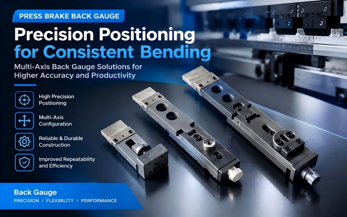
For manufacturers evaluating a replacement or retrofit solution, MIHARTING's press brake back gauge systems provide an option to consider alongside the required axis configuration, working range, finger arrangement, CNC compatibility, and positioning requirements.
A calibration check should begin with the machine in a known condition and should follow the manufacturer's service procedure.
Start by inspecting the back gauge mechanically. Check the fingers, mounts, guides, and other accessible components for obvious looseness, damage, contamination, or abnormal movement.
Next, establish a consistent measurement reference.
Command a known X-axis position and measure the actual physical position of the back gauge. Repeat the same movement several times.
Then test additional positions across the normal working range.
For example:
50 mm → 100 mm → 200 mm → 400 mm
The exact values should be selected according to the machine's travel and service requirements.
Record both the commanded and measured positions.
What matters most is the pattern.
If the results look like:
50 → 50.8 mm
100 → 100.8 mm
200 → 200.8 mm
400 → 400.8 mm
the error is relatively consistent.
If they look like:
50 → 50.1 mm
100 → 100.4 mm
200 → 201.0 mm
400 → 402.0 mm
the increasing error deserves a different investigation.
After the positioning check, verify finger alignment and perform a controlled test bend using the normal tooling and material.
This provides a much clearer picture than changing a production program and checking only one finished part.
The appropriate response depends on what the diagnostic measurements show.
Calibration is appropriate when the machine is mechanically stable but the coordinate-to-position relationship is consistently offset.
Repair is appropriate when mechanical play, wear, alignment problems, or positioning-system faults prevent repeatable movement.
Replacement becomes relevant when the existing system cannot maintain the required performance or critical components are no longer practical to maintain.
Upgrade may be appropriate when the existing back gauge lacks the axis configuration, finger capability, positioning performance, or automation required by current production.
The distinction is important because repeatedly recalibrating a mechanically worn back gauge does not solve the underlying problem.
There is no universal calibration interval for every press brake. The appropriate frequency depends on machine usage, production requirements, environmental conditions, maintenance history, and the manufacturer's recommendations.
A calibration check is particularly worthwhile after major service work, encoder or drive replacement, machine relocation, or unexplained dimensional changes.
The CNC value represents the programmed position, not necessarily the final physical flange dimension.
Check the actual back gauge position, finger alignment, sheet contact, tooling, material condition, and bending process before changing the X-axis parameter.
No. If the gauge physically moves because of mechanical looseness, calibration cannot remove that movement.
The mechanical problem should be identified and corrected before calibration.
Command several known positions and independently measure the physical gauge position using a suitable reference method.
Repeat each position and compare the measured values with the commanded coordinates. Follow the machine manufacturer's calibration procedure for the exact measurement method and reference point.
The fingers may be misaligned, mounted differently, worn, or mechanically loose.
Check their physical positions and contact surfaces before changing the global X-axis calibration.
Yes.
A correctly positioned back gauge does not eliminate dimensional variation caused by material properties, springback, tooling, die opening, bend sequence, workpiece movement, or other process factors.
Replacement should be considered when mechanical wear or component problems prevent the gauge from maintaining repeatable positioning after appropriate service.
An upgrade may be more appropriate when the current back gauge still functions but lacks the positioning axes or capabilities required for newer production requirements.
Press brake back gauge calibration should be approached as a measurement and troubleshooting task rather than simply a CNC parameter adjustment.
A consistent offset between the programmed X-axis value and the physical gauge position may indicate a calibration issue. Increasing error across travel can point toward positioning or mechanical problems. Different results between the left and right fingers may indicate alignment issues, while random variation can be caused by mechanical play, sheet movement, tooling, or material conditions.
The most effective approach is to verify the physical position first, repeat the measurement at multiple points, inspect the fingers and mechanical components, and only then determine whether calibration is required.
When the system is mechanically stable and the error is repeatable, calibration may restore the required positioning accuracy. When the gauge cannot maintain its position, mechanical repair should come first. And when production requirements have outgrown the existing system, replacement or an upgraded back gauge may provide a more practical long-term solution.
For manufacturers evaluating positioning equipment, MIHARTING's press brake back gauge solutions can be evaluated according to the machine's required axis configuration, finger arrangement, working range, CNC compatibility, and positioning requirements.
https://www.bystronic.com/usa/en-us/news/240220-press-brake-essentials
https://www.lvdgroup.com/en-us/press-brakes/stand-alone-press-brakes/pped
https://www.amada.com/america/TEXT%20FILES/how_to_deal_with_angular_variation_on_the_press_brake.pdf
 Press Brake Tooling: Releasing the Brake for AerospaceJuly 25, 2025Why Aerospace Manufacturing Demands Next-Generation Press BrakesThe aerospace industry operates on razor-thin tolerances where a 0.1mm deviation can compromise entire assemblies.view
 Selecting the Right Shearing Machine Blade: A Guide to Material Grades and Blade Gap OptimizationApril 22, 2026The shear is the “entry point” of the fabrication shop. If the initial cut is burred, twisted, or bowed, every subsequent process—from CNC punching to bending—will be inaccurate. MIHARTING shearin...view
 What Special Requirements Do Titanium Alloys and Composite Materials Have for the Design of Bending Machine Molds?June 26, 2025Titanium Alloy:1. Due to the high hardness of titanium alloys, mold design needs to consider the use of specially designed structures and processes to adapt to its bending characteristics. The choice ...view
 How Press Brake Quick Clamping Systems Reduce Setup Time by 80%September 7, 2026For many sheet metal manufacturers, press brake setup is an overlooked source of production downtime.A faster clamping system can therefore reduce both labor time and machine downtime.view
 Understanding EN 12622: How CE-Compliant Press Brakes Protect European OperatorsSeptember 14, 2026Understand EN 12622 press brake safety requirements, including laser protection, guarding, emergency stops and safety controls, and what European buyers should check for CE compliance.view
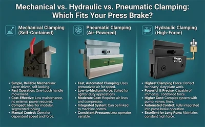 Mechanical vs. Hydraulic vs. Pneumatic Clamping: Which Fits Your Press Brake?September 8, 2026Choosing a press brake quick clamping system is not simply about finding the fastest option.Mechanical, pneumatic and hydraulic clamping systems each have different advantages.The right choice depends on your tooling, production volume, tool-change frequency and machine configuration.view