EN
EN

A proportional valve is an electrically controlled valve that continuously regulates fluid flow, pressure, or direction according to a variable command signal. Unlike a conventional on/off valve, which normally switches between fixed states, a proportional valve can operate at many intermediate positions. This allows a hydraulic or pneumatic system to change actuator speed, force, pressure, or movement more smoothly and precisely.
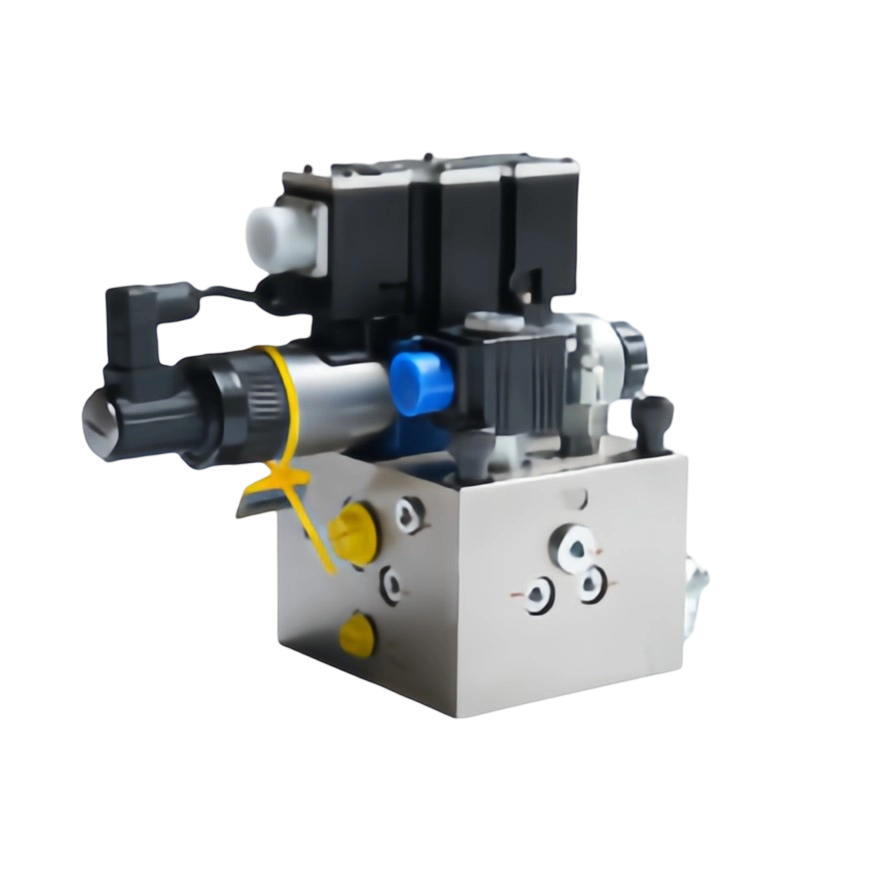
In industrial hydraulic equipment, a proportional valve acts as the link between an electronic controller and the fluid-power circuit. The controller sends a variable electrical command, the valve converts that command into movement of a spool or poppet, and the resulting change in opening area controls the hydraulic output. This is why proportional valves are widely used when a machine needs more than simple start-stop control.For press brake applications, explore our press brake proportional valves and check the required electrical and hydraulic specifications.
Proportional valve definition: a proportional valve is a control valve whose hydraulic or pneumatic output changes in relation to a continuously variable electrical input signal.
The practical proportional valve meaning is easier to understand by comparing it with a light switch and a dimmer. A basic solenoid valve behaves more like a switch: it changes from one defined state to another. A proportional valve behaves more like a dimmer because the command can be increased or reduced progressively, allowing the valve opening and resulting fluid output to be adjusted across a usable range.
The word “proportional” does not mean that every valve is perfectly linear under every operating condition. Actual flow and pressure are also influenced by valve design, pressure differential, fluid properties, electronics, hysteresis, dead band, temperature, and the load on the actuator. The important principle is that the valve accepts a variable command and provides a controllable intermediate output rather than only fully open or fully closed operation.
Depending on the design, the moving control element may be a spool, poppet, or another metering element. In many hydraulic proportional valves, an electrical current acts on a proportional solenoid. That electromagnetic force moves the internal control element and changes the effective opening through which oil can flow.
A proportional valve works by converting a variable electrical command into controlled mechanical movement inside the valve, which then changes hydraulic flow, pressure, or direction.
The control process normally begins with a machine controller, PLC, CNC, or dedicated valve driver. The controller sends a command signal to the valve electronics. Depending on the valve model, common industrial command interfaces can include 0–10 V, plus/minus 10 V, 0–20 mA, or 4–20 mA. The electronics regulate the current supplied to the proportional solenoid, and the resulting magnetic force moves the spool or poppet toward the commanded position.
As the internal element moves, the metering area between hydraulic ports changes. A larger opening generally allows more fluid to pass under the same pressure conditions, while a smaller opening restricts flow. In a directional proportional valve, spool movement also determines which ports are connected, so the same valve can influence both direction and flow to an actuator.
Some proportional valves use open-loop control, where the commanded current is applied without continuously measuring the actual spool position. Higher-performance designs may use closed-loop spool-position feedback. In those valves, an internal position sensor measures actual spool travel, the electronics compare it with the command, and the drive current is corrected until the requested position is reached more accurately.
The proportional valve working principle is the controlled conversion of an electrical setpoint into a corresponding valve opening, so that fluid-power output can be adjusted continuously rather than switched only between fixed states.
At the electrical stage, a command signal represents the requested operating condition. At the electromagnetic stage, the proportional solenoid converts electrical current into force. At the mechanical stage, that force shifts a spool or acts on a poppet. At the hydraulic stage, the resulting change in the metering opening controls flow or pressure. The actuator then responds according to the hydraulic output.
This relationship is why proportional control is useful in machines that need smooth acceleration, controlled deceleration, adjustable force, pressure ramps, or different speeds during separate portions of a machine cycle. The controller does not need to select only “on” or “off”; it can command intermediate values that match the process requirement.
However, engineers should not assume that an electrical command always produces exactly the same hydraulic result under all conditions. For a flow-control function, the pressure difference across the metering edge can affect the actual flow. For a pressure-control function, spring forces, hydraulic forces, and load conditions influence equilibrium. This is why valve selection must consider the hydraulic circuit as a whole rather than only the input signal.
The main proportional valve function is to convert a variable electrical command into a controlled fluid-power output that can regulate actuator motion, pressure, force, speed, or direction.
In a flow-control application, the valve adjusts how much fluid reaches an actuator, which can be used to control cylinder or motor speed. In a pressure-control application, it changes the pressure setpoint in response to an electrical command, allowing machine force or clamping pressure to be adjusted during operation. In a directional-control application, it can regulate both the direction of fluid movement and the degree of opening between ports.
The advantage is not simply “more precision.” The more important benefit is controllability throughout a machine cycle. A hydraulic axis may need a rapid approach, a slower working movement, a controlled pressure-building stage, and a smooth return. Proportional control allows the machine controller to command different operating levels at different stages instead of relying only on fixed mechanical adjustments.
A proportional valve diagram should show how an electrical command passes through the valve-control chain and becomes hydraulic motion at the actuator.
Basic control sequence: Machine controller or CNC → valve driver or onboard electronics → proportional solenoid → spool or poppet → variable metering opening → hydraulic flow or pressure → cylinder or hydraulic motor.
Stage | What Happens | Why It Matters |
1. Controller | The PLC, CNC, or motion controller calculates the required operating command. | Defines the desired speed, pressure, force, or movement for the current machine stage. |
2. Electrical command | A voltage or current signal is sent to the valve electronics. | Provides a variable setpoint instead of a simple on/off instruction. |
3. Proportional solenoid | Electrical current is converted into electromagnetic force. | Creates the force needed to reposition the internal valve element. |
4. Spool or poppet movement | The control element moves to change the valve opening. | Determines which flow paths are open and how large the effective metering area becomes. |
5. Hydraulic output | Flow, pressure, or direction changes in the circuit. | Controls actuator speed, force, or movement. |
6. Feedback, if equipped | A spool-position or system sensor sends an actual-value signal back to the control electronics. | Allows the controller to correct deviations and maintain more accurate output. |
A proportional valve schematic uses standardized hydraulic symbols rather than a physical cross-section. When reading a schematic, identify the pressure port, tank port, working ports, normal spool position, actuation method, and the type of proportional control. The schematic shows how the valve fits into the circuit, while the functional diagram above explains how the command is converted into motion.
The main proportional valve types are proportional directional valves, proportional pressure valves, and proportional flow-control valves, each designed to regulate a different hydraulic variable.
Valve Type | Main Controlled Variable | Typical Machine Function | Selection Focus |
Proportional directional valve | Direction and metered flow between ports | Controlling actuator movement and speed in both directions | Spool configuration, nominal size, flow capacity, pressure rating, command signal, feedback |
Proportional pressure valve | Pressure | Adjusting system pressure, force, relief setting, or pressure reduction | Pressure range, flow range, response, minimum pressure, electrical interface |
Proportional flow-control valve | Flow rate | Changing cylinder or motor speed | Required flow range, pressure compensation, pressure drop, response, fluid condition |
The correct type depends on what the machine needs to control. If the requirement is adjustable cylinder speed, flow control may be central to the solution. If the requirement is adjustable force, pressure control is more important. If both movement direction and speed must be controlled through the same element, a proportional directional valve may be appropriate.
A proportional valve provides continuously variable control between basic on/off solenoid control and the very high dynamic precision associated with many servo-valve applications.
Feature | Conventional Solenoid Valve | Proportional Valve | Servo Valve |
Primary control style | Usually discrete switching | Continuously variable | Continuously variable, typically optimized for high-performance closed-loop control |
Intermediate positions | Limited or not intended as the main operating mode | Yes | Yes |
System complexity | Low | Moderate | High |
Typical application | Start/stop and directional switching | Adjustable speed, pressure, force, and motion | Highly dynamic precision motion-control systems |
Contamination sensitivity | Application dependent | Requires appropriate hydraulic cleanliness | Often requires especially strict fluid cleanliness |
Cost and commissioning effort | Generally lowest | Middle range | Generally highest |
A proportional valve is therefore not automatically the “better” choice for every circuit. If an actuator only needs to extend and retract at a fixed speed, a conventional solenoid valve may be simpler and more economical. Proportional control becomes valuable when the machine needs adjustable or staged behavior. Servo valves are normally considered when dynamic response and closed-loop accuracy requirements justify a more complex solution.
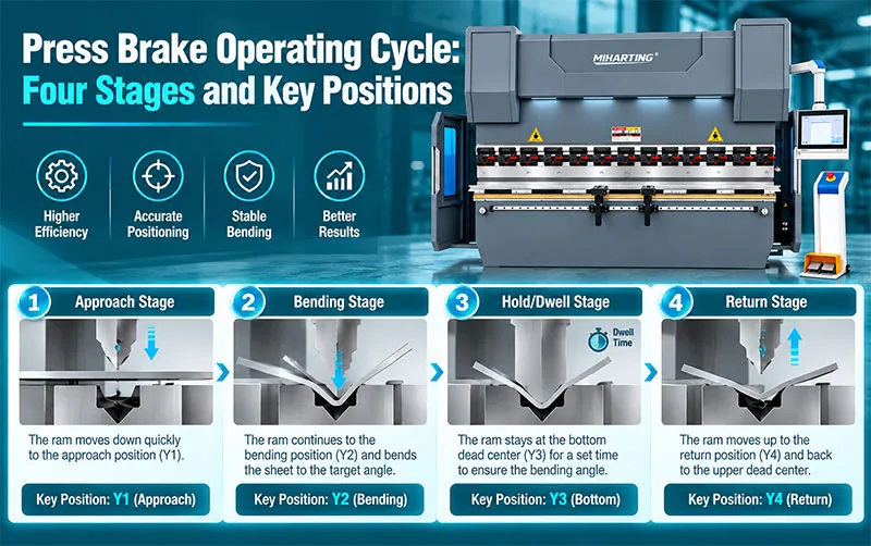
In a hydraulic press brake, proportional valves help the control system regulate hydraulic conditions during different stages of ram movement, including approach, bending, pressure control, and return.
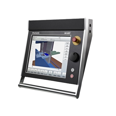
The press brake controller calculates the required movement and operating sequence, then sends commands to the hydraulic control components. A suitable press brake controller can coordinate axis commands with hydraulic valve control so that ram movement follows the programmed bending cycle.
During the fast-approach stage, the machine may require relatively high cylinder speed. As the upper beam approaches the workpiece, the control strategy changes to a slower and more controlled bending speed. During forming, pressure must rise in a controlled way to create the required force. The hydraulic system then manages decompression and return movement after the bend. Proportional valves allow these transitions to be controlled electronically instead of relying only on fixed valve states.
The valve is only one part of the machine. Hydraulic performance also depends on pumps, cylinders, seals, filtration, sensors, controllers, manifolds, and other press brake accessories. Accurate bending also depends on the mechanical condition of the machine and the correct selection and alignment of press brake tooling. For this reason, a valve problem should not be diagnosed from bend quality alone.
Proportional valve performance depends on the interaction between electrical command quality, valve condition, hydraulic pressure, fluid cleanliness, temperature, circuit design, and actuator load.
The command signal must match the valve electronics. A valve designed for a 0–10 V input should not be treated as though it uses the same interface as a 4–20 mA model. Some proportional directional valves also use bipolar command signals such as plus/minus 10 V so that signal polarity determines direction while signal amplitude determines spool displacement. Always confirm the exact interface and wiring from the valve documentation.
Flow through an orifice depends not only on opening area but also on the pressure difference across the metering edge. This means that the same spool position can produce different flow under different pressure conditions unless the valve or circuit includes suitable pressure compensation or closed-loop control.
Small clearances are necessary for precise metering, so contaminated oil can cause wear, sticking, unstable movement, or sluggish spool response. A recurring proportional-valve fault should therefore trigger a review of filtration, oil condition, contamination sources, and the cleanliness of the hydraulic circuit rather than only replacement of the electrical coil.If cleaning and electrical checks do not resolve the fault, record the valve model and machine symptoms before contacting our team about a replacement.
Hydraulic-fluid viscosity changes with temperature. A system that behaves differently when cold and warm may be affected by fluid condition, temperature, valve characteristics, or other components in the circuit. Stable machine operation requires the valve to be selected for the actual operating environment and maintained within the fluid specifications of the hydraulic system.
Common proportional valve problems include no response, slow or inconsistent response, unstable actuator movement, incorrect pressure or speed, and excessive drift from the commanded operating point.
Symptom | Possible Causes | What to Check First |
No valve response | No supply voltage, missing enable signal, wiring problem, incorrect command, failed electronics, mechanical sticking | Power supply, enable circuit, command signal, connector condition, fault indicators |
Slow or sluggish movement | Contamination, sticky spool, incorrect oil viscosity, low pressure, restricted flow path | Oil condition, filtration, pressure, valve cleanliness, machine temperature |
Unstable or oscillating motion | Noisy command signal, poor tuning, air in the system, unstable pressure, sensor or feedback issue | Signal quality, controller settings, hydraulic pressure, air removal, feedback signal |
Incorrect pressure or speed | Wrong valve range, incorrect parameter setting, excessive leakage, pressure variation, load change | Valve specification, command scaling, system pressure, leakage, actuator load |
Valve overheats | Electrical overload, continuous high current, internal sticking, incorrect voltage, poor heat dissipation | Coil rating, supply voltage, driver current, valve movement, ambient conditions |
Troubleshooting should be systematic. First determine whether the problem is electrical, hydraulic, mechanical, or control-related. Measure the command signal rather than assuming that the controller is sending the intended value. Confirm pressure and flow conditions rather than replacing the valve immediately. If contamination is suspected, investigate the reason for contamination and review filtration before returning the machine to service.
Selecting a proportional valve requires matching its hydraulic capacity, control function, electrical interface, and dynamic characteristics to the actual machine circuit.
Start with the function. Decide whether the application needs pressure control, flow control, directional control, or a combination. Then determine the required pressure range and maximum flow. A valve that is too small can create excessive pressure loss and limit machine performance; a valve that is unnecessarily large may reduce control resolution and increase cost.
Next, confirm the electrical interface. The machine controller and valve electronics must use compatible command and feedback signals. Check supply voltage, input signal type, connector, enable logic, and whether the valve uses onboard electronics or an external amplifier.
Machine compatibility is equally important. Confirm mounting pattern, port arrangement, nominal size, seal material, fluid compatibility, operating temperature, and the hydraulic circuit configuration. For replacement work, the old valve code should be checked carefully because visually similar valves can have different spool functions, pressure ranges, electronics, or fail-safe positions.
For press brake replacement and maintenance projects, MIHARTING can help customers identify compatible hydraulic components based on machine model, existing valve information, photos, nameplate data, and control requirements. Buyers who are comparing a proportional valve for sale should confirm technical compatibility before placing an order rather than selecting only by appearance or connector shape.
A proportional valve should be considered for replacement when verified electrical and hydraulic checks show that the valve can no longer respond consistently to its command or maintain the required pressure, flow, or spool position.
Replacement should not be the first diagnostic step. Problems that appear to be valve faults can originate from contaminated oil, wiring, a faulty driver, incorrect parameter settings, weak hydraulic pressure, cylinder leakage, or sensor problems. A replacement decision is stronger when the command signal is correct, supply conditions are within specification, the hydraulic system is clean, and the valve still produces unstable or insufficient output.
For older equipment, replacement can also be necessary when the original valve is obsolete. In this situation, selecting an alternative requires more than matching port size. The replacement should reproduce the required hydraulic function, electrical control method, flow and pressure capacity, mounting interface, and safe power-down behavior.
A proportional valve is a valve that can open or regulate its output by different amounts according to an electrical command. Instead of only switching on or off, it can provide intermediate control of hydraulic or pneumatic flow, pressure, or direction.
Its main function is to convert a variable electrical setpoint into a controlled fluid-power output. Depending on the valve type, that output can regulate flow, system pressure, actuator speed, force, or direction.
A conventional solenoid valve is usually intended to switch between defined positions. A proportional valve is designed to operate through a range of intermediate positions, allowing the controller to vary hydraulic or pneumatic output continuously.
The exact signal depends on the valve electronics. Common industrial examples include 0–10 V, plus/minus 10 V, 0–20 mA, and 4–20 mA. Always confirm the required signal, supply voltage, and wiring from the specific valve documentation.
Yes. When the valve controls or meters flow to a hydraulic cylinder, changing the valve opening can change the cylinder speed. Actual speed also depends on load, pressure, circuit design, cylinder dimensions, and whether the system compensates for pressure changes.
Possible causes include contaminated hydraulic oil, a sticky spool, unsuitable viscosity, electrical problems, low system pressure, or a restricted flow path. The correct troubleshooting process checks both the command signal and the hydraulic system before deciding that the valve itself has failed.
A proportional valve gives a machine controller continuous influence over hydraulic or pneumatic output. Its defining characteristic is the ability to convert a variable electrical command into a corresponding change in valve position, flow, pressure, or direction. That makes proportional control valuable for industrial equipment that requires adjustable speed, staged pressure, controlled force, or smooth motion rather than simple on/off operation.
For press brake users, understanding the valve is especially useful when diagnosing inconsistent ram movement, pressure-control problems, retrofit requirements, or hydraulic component replacement. The valve should always be evaluated as part of the complete control and hydraulic system. MIHARTING supports press brake maintenance and component selection with proportional valves, controllers, tooling, and related machine accessories for sheet-metal bending applications.
Parker Hannifin, Proportional Directional Control Valve Operation Manual, Series DFplus: https://www.parker.com/content/dam/Parker-com/Literature/Industrial-Systems-Division-Europe/Manuals-UK/PDF/D_F_30-5715-687-UK.pdf
Bosch Rexroth, Hydraulic Proportional Valves and Proportional Solenoid Technical Information: https://www.boschrexroth.com/en/at/c/valves/
Festo, Proportional Valves and Analogue Setpoint Interfaces: https://www.festo.com/us/en/c/products/valves-and-valve-manifolds/proportional-valves-id_pim120
 Complete Guide to Press Brake Dies: Types, Materials and ApplicationsAugust 14, 2026A press brake die is one of the most important components in the bending process. While the machine provides the bending force, the die determines how the sheet is supported and formed.view
 Understanding EN 12622: How CE-Compliant Press Brakes Protect European OperatorsSeptember 14, 2026Understand EN 12622 press brake safety requirements, including laser protection, guarding, emergency stops and safety controls, and what European buyers should check for CE compliance.view
 What Is Press Brake Tooling and How Does It Work?January 8, 2026In the world of metal fabrication, press brake tooling stands as a cornerstone of efficiency and precision, crucial for bending operations in various industries. Understanding the complex orchestratio...view
 Press Brakes Don't Just Bend Metal - They Bend the RulesJuly 25, 2025The Basics and Trends of Sheet Metal Manufacturing IndustrySheet metal remains the backbone of countless industries, from automotive frames to aerospace components.view
 China Press Brake Tooling Manufacturer vs European SuppliersSeptember 4, 2026Compare China press brake tooling manufacturers with European suppliers in quality, compatibility, customization, lead time, service and total cost.view
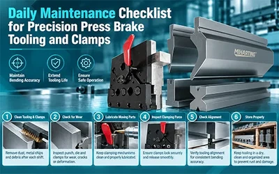 Daily Maintenance Checklist for Precision Press Brake Tooling and ClampsSeptember 29, 2026Precision tooling cannot maintain accurate bends if dirt, rust, wear, or loose components are ignored. A simple daily checklist helps you protect your tooling, clamps, bending accuracy, and production stability.view