EN
EN

Ordering replacement tooling for an older press brake is rarely as simple as identifying the machine brand and sending a photograph of the existing punch. In many fabrication shops, the original tooling drawing is no longer available, identification marks have worn away, or the customer simply has a machine model, an old punch and die, and a few photographs.
That does not necessarily make replacement impossible. In fact, a physical tool can provide a large amount of useful engineering information when it is measured correctly.
The important point is to separate three things that are often confused during a tooling inquiry: machine compatibility, tool geometry, and bending requirements. The machine model helps identify the general tooling system. Measurements of the existing punch and die establish the physical interface and working dimensions. Information about the material and finished part confirms whether the existing geometry is actually appropriate for the application.
This distinction is particularly important when replacing tooling for machines from AMADA, Bystronic, LVD or other established press brake manufacturers. Modern tooling systems can differ in punch height, clamping method, segmentation, die configuration and working geometry, so the machine brand alone cannot define the complete replacement specification.
The machine should be the first reference point when preparing a replacement tooling request.
Record the manufacturer, exact model, nominal tonnage, working length and, if available, the machine serial number or year of manufacture. A photograph of the machine nameplate is often preferable to manually entering the information because it provides a direct reference for the manufacturer and model designation.
However, the machine model should be treated as the beginning of the investigation rather than the final answer.
AMADA, for example, currently offers different press brake tooling configurations, including fixed-height tooling, Euro-style tooling and different punch-holder arrangements. Its AFH tooling uses a consistent 120 mm punch height, while other tooling systems have different configurations.
The same principle applies to other machine manufacturers. LVD offers standard, hemming and custom tooling, while its tooling is designed for machines covering a wide range of capacities.
For this reason, a request such as "I have an AMADA press brake and need a replacement punch" does not provide enough engineering information. The exact machine and the physical tooling interface still need to be confirmed.
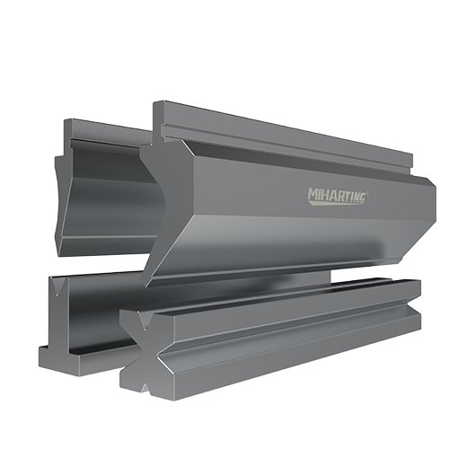
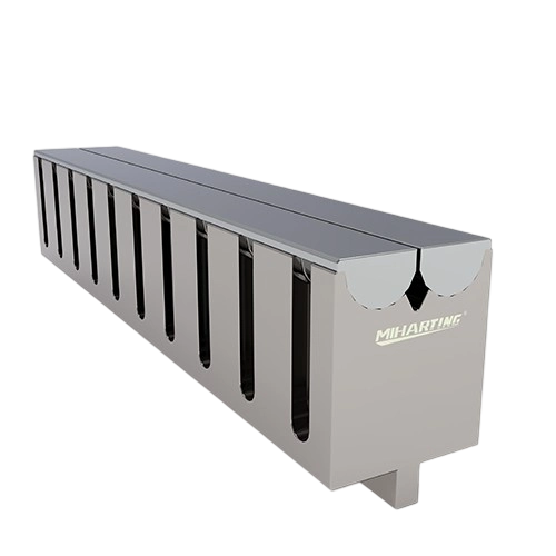
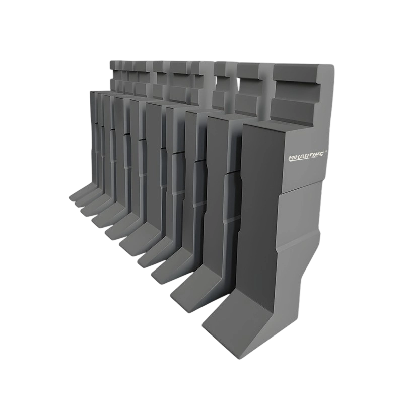
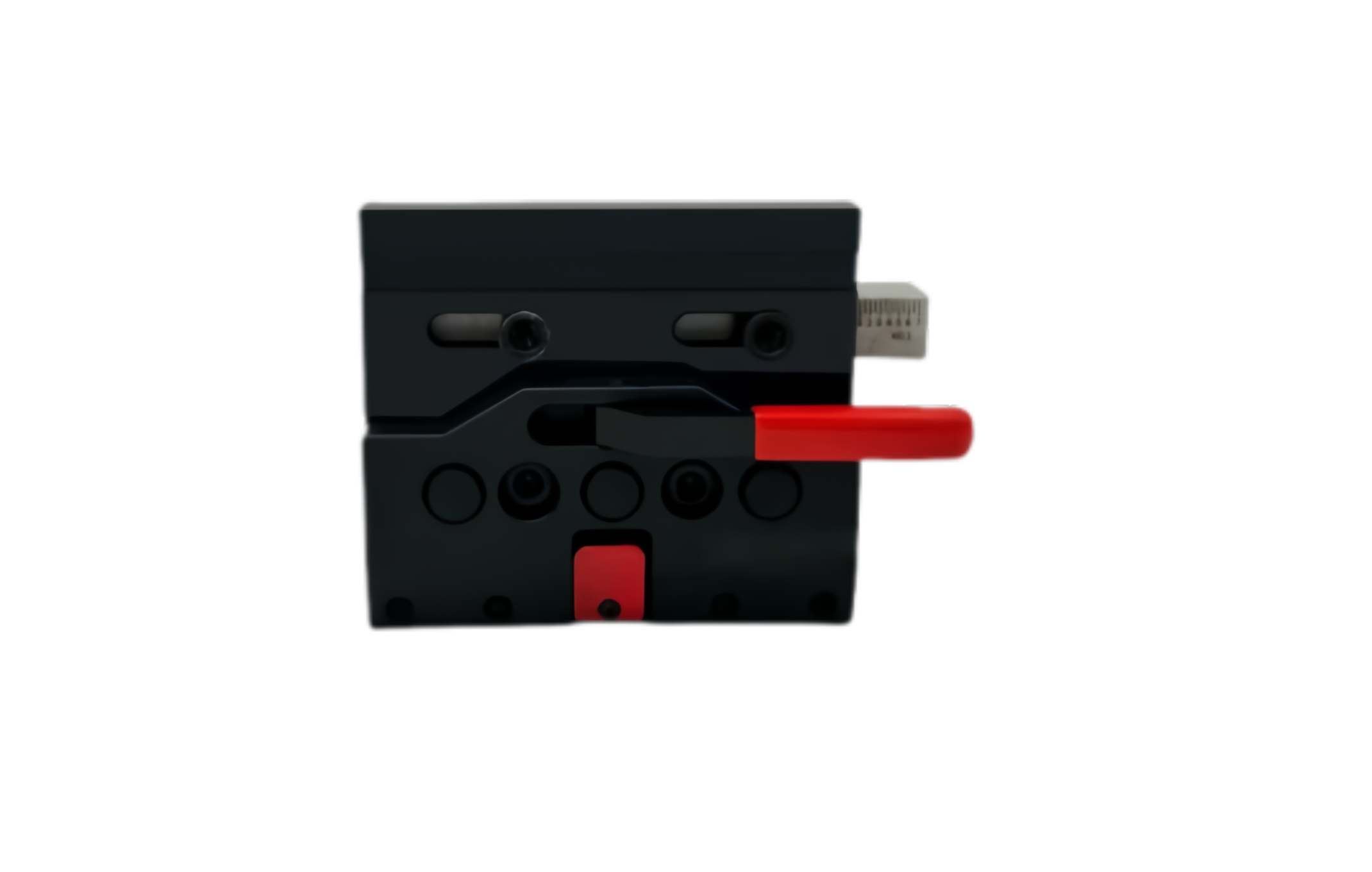
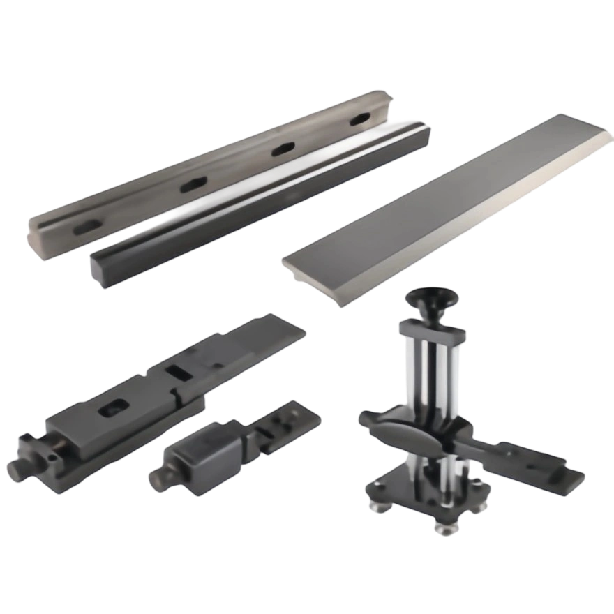
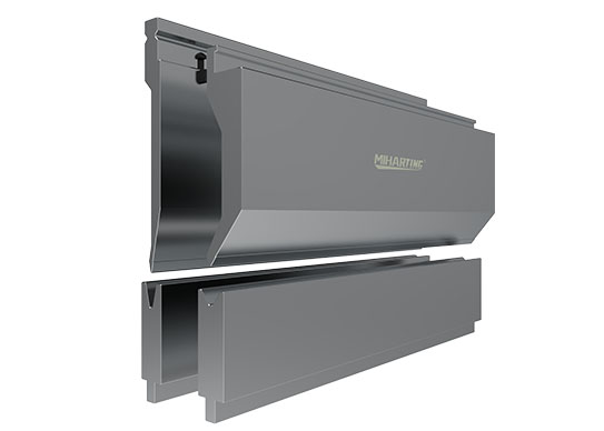
For customers who are beginning the process, the best starting point is to review the available press brake tooling options and then compare the machine-side interface with the existing tool.
.jpg "press brake tooling")
The machine-side interface is one of the most important parts of the entire measurement process.
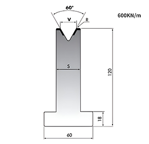
Before measuring the punch tip, examine the portion of the tool that connects to the upper clamping system. Depending on the tooling design, this area may include a mounting shoulder, retaining groove, locating surface, tang or another specialized interface.
This is where many replacement-tooling mistakes begin. A punch can look almost identical to the original while having a different mounting geometry. If that interface is wrong, the tool may not seat correctly even when its angle, radius and overall appearance seem appropriate.
Measure the width, depth, height and relevant locating surfaces of the mounting section. If there is a retaining feature, record its position relative to the main body of the punch.
A side-view photograph is extremely useful because it shows the relationship between the mounting interface and the working section. If possible, photograph the punch both installed in the machine and after removal.
The installed photograph is particularly valuable when the clamping arrangement is difficult to identify from the tool alone.
A professional CAD drawing is not always necessary for a replacement tooling inquiry.
A clear hand sketch can be sufficient if the reference points and dimensions are easy to understand. The drawing should show the overall punch profile and identify the machine-side interface, overall height, major widths, working length and tip geometry.
The most important principle is consistency.
If the overall height is measured from the bottom of the punch body to the tip, state that clearly. If a width is measured between two shoulders, identify those shoulders on the sketch. Avoid dimensions that are visually obvious but have no defined reference surface.
Photographs should accompany the sketch. The drawing provides numerical information, while the photograph provides context.
This combination is especially useful for older tooling where the original manufacturer drawing may no longer be available.
Tool height is more than a simple overall dimension.
The height determines how the punch sits within the press brake tooling system and influences the available bending envelope. A replacement punch with a different height can change the relationship between the punch, die, workpiece and machine.
AMADA's current tooling range demonstrates why height needs to be treated as a specific engineering parameter. Its AFH tooling uses a common punch height, while other tooling systems have different configurations and applications.
When measuring an existing punch, identify the reference surface from which the height is being measured. Record the overall height and, where relevant, the height of important shoulders or locating surfaces.
Do not assume that two punches are interchangeable simply because their working tips have the same angle.
If the customer is replacing a complete tooling set, the relationship between punch height and die height should also be considered. The objective is to reproduce a functioning tooling setup rather than simply match one isolated dimension.
Length is another dimension that can cause confusion.
A tooling set may consist of one continuous punch or several segmented pieces. The total working length may therefore be different from the length of an individual segment.
If the existing tooling is segmented, photograph the complete arrangement before separating the sections. Record the total installed length and, where practical, the length of each individual segment.
This information matters when the customer expects the replacement tooling to reproduce an existing setup. A manufacturer needs to know whether the requirement is for a single continuous tool, a standard segmented set or a particular combination of segments.
The same consideration applies to dies. Some applications use continuous dies, while others use sectionalized components or special lower-tool arrangements.
A useful replacement request should therefore describe not only how long the tool is, but also how that length is constructed.
Once the machine interface and tool height have been established, attention can move to the working geometry.
The punch angle determines the shape and contact condition of the working tip. The tip radius affects the interaction between the punch and the material and can influence the resulting bend geometry.
These dimensions should not be estimated casually from a photograph.
If the original drawing is available, use the specified dimensions. If the drawing is missing, measure the existing tool as accurately as possible. Where the radius cannot be measured reliably, provide a clear close-up photograph and identify the value as uncertain rather than presenting an estimate as a confirmed specification.
This distinction becomes important when the original punch is worn. A worn radius may no longer represent the intended manufacturing dimension.
The objective of replacement tooling is not always to copy the worn tool exactly. If the existing tool has produced satisfactory parts, its geometry can provide a strong reference. If it has already caused bending problems, the replacement should instead be evaluated against the required finished-part dimensions.
The lower die should be measured independently from the punch.
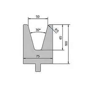
The key dimensions normally include the die height, overall width, V-opening, die angle, working length and lower mounting interface. Depending on the design, there may also be multiple V-openings, special shoulders, replaceable inserts or other features.
Among these dimensions, the V-opening deserves particular attention.
The V-opening influences the relationship between material thickness, bend radius, flange dimensions and required bending force. It should therefore be measured rather than selected simply because it is commonly used on a particular machine.
When an existing die is available, measure the actual V-opening and included angle. If the die is heavily worn or damaged, photograph the opening from several angles and provide information about the material being bent.
A manufacturer can then determine whether the existing geometry should be reproduced or whether a different die configuration would be more appropriate.
One of the most common mistakes in replacement tooling procurement is to associate a machine brand with a specific die opening.
The machine does not determine the V-opening by itself.
Material thickness, material strength, desired inside bend radius, flange dimensions, bending method and machine capacity all influence die selection. The same press brake may therefore use different die openings for different production jobs.
This is why the application should be included in a replacement tooling inquiry whenever the original die specification is uncertain.
If the customer is bending 3 mm mild steel, for example, the tooling requirements may differ from an application involving 3 mm stainless steel or high-strength steel. The material, required radius and part geometry provide information that a machine model cannot provide.
For an existing tool that has been used successfully, the original V-opening remains an important reference. But when changing materials or part geometry, it should not automatically be treated as the ideal replacement specification.
The top of the die gets most of the attention because the V-opening is visible. The lower interface is just as important for compatibility.
Measure the width and height of the die base and record any locating grooves, shoulders, retaining features or special mounting geometry.
If the die sits inside a separate holder, photograph both the die and the holder. In some installations, the holder provides the actual machine interface while the die insert provides the working geometry.
A replacement die with the correct V-opening can still be unusable if the bottom profile does not match the existing support.
This is one reason replacement tooling should always be considered as a complete mechanical interface rather than simply a punch or die profile.
When a customer has no tooling drawing, good photographs can dramatically improve the accuracy of the quotation.
For the punch, provide a full side view, a close-up of the mounting area and a close-up of the working tip. If possible, include a photograph of the punch installed in the press brake.
For the die, photograph the complete profile, the V-opening and the lower mounting surface. If the die is installed in a holder, include the holder in at least one photograph.
The photographs should be taken as square to the tooling as possible. Extreme angles can make shoulders and dimensions appear distorted.
Any identification numbers, engraved marks, manufacturer symbols or stamped codes should also be photographed clearly.
A photograph should not replace measurement, but it can explain a measurement in a way that a number alone cannot.
The existing tooling describes what the customer currently owns. The finished part describes what the customer actually needs.
This distinction becomes important when the original tooling has been modified, worn or incorrectly selected.
Provide the material grade and thickness, required bend angle, inside bend radius, flange dimensions and approximate bending length. If a part drawing exists, it should be included with the tooling inquiry.
For box-shaped components or parts with return flanges, photographs of the finished component can also be useful. They show how much clearance the punch needs and whether the existing tooling geometry is suitable for the bending sequence.
This application information can prevent a common purchasing error: reproducing an old tool exactly even though the customer's current production requirements have changed.
A replacement tool should restore the required bending process, not simply reproduce a historical dimension set.
A missing drawing is not necessarily a problem.
Start with the machine identification. Then photograph the old punch and die from multiple angles. Measure the machine-side interfaces, overall heights, working lengths and major working dimensions.
If the tool has an identification number, include it. If the punch or die is still installed in the machine, photograph the installed position before removing it.
Next, provide information about the part being produced. The material, thickness, bend angle and inside radius can help a tooling manufacturer evaluate whether the existing dimensions are appropriate.
This is particularly useful when the customer is replacing obsolete tooling. The goal may be to reproduce the original geometry, but it may also be an opportunity to adapt the tooling to current production requirements.
MIHARTING currently supplies press brake tooling for several major machine-tooling systems and lists AMADA, BYSTRONIC and LVD tooling among its product categories.
Worn tooling should be documented differently from new or lightly used tooling.
Do not assume that the most visible dimension represents the original design dimension. Repeated bending can change the punch tip, die shoulders and working surfaces. Local damage can also create measurements that differ significantly from the intended specification.
Photograph worn areas closely and indicate where the wear is located.
If the tool still produces acceptable parts, tell the manufacturer. If the tool is already producing inconsistent bend angles, incorrect radii or dimensional variation, that information is equally important.
For example, a worn punch tip may have a larger effective radius than its original specification. Copying the worn profile without considering the finished part could therefore reproduce the problem rather than solve it.
The best replacement specification combines the condition of the old tool with the requirements of the current production process.
The most important dimensions are the ones that determine whether the tool can be installed and whether it can produce the required bend.
| Dimension | Why It Matters | What to Provide |
|---|---|---|
| Punch interface | Determines upper-tool compatibility | Mounting profile, shoulders and retaining features |
| Punch height | Establishes working position | Defined reference-to-tip measurement |
| Punch angle | Determines working geometry | Actual tip angle |
| Punch radius | Influences bend geometry | Radius measurement or close-up profile |
| Punch length | Determines usable bending area | Overall and sectional length |
| Die V-opening | Influences bend radius and force | Actual V width |
| Die angle | Defines the lower-tool geometry | Included angle |
| Die height | Affects setup and working envelope | Reference surface to top of die |
| Die interface | Determines lower-tool compatibility | Base width, height and locating geometry |
The purpose of this table is not to encourage customers to measure every possible feature. It is to show which information normally has the greatest influence on a replacement decision.
A good replacement tooling request does not need to be complicated.
The first section should identify the machine. The second should describe the existing tooling. The third should describe the finished part and material.
For an AMADA machine, the request could include the machine model, tooling photographs, punch interface dimensions, punch height, working length, tip radius, die V-opening and material specification.
For a Bystronic machine, the clamping arrangement and tooling configuration should be clearly identified because the tooling system can affect the required interface. MIHARTING's current product range includes several Bystronic punch configurations with different angles, radii and heights, illustrating why the machine brand alone does not define the complete specification.
For an LVD machine, the exact tooling configuration should also be verified. LVD itself offers standard tooling as well as hemming and custom tools, demonstrating that tooling requirements can extend beyond a single standard profile.
This information allows a manufacturer to evaluate the request as an engineering problem rather than simply matching a photograph against a catalogue.
A standard replacement is generally appropriate when the machine interface, tool geometry and application are already well defined.
If the existing punch and die are standard, the machine tooling system is confirmed and the customer is simply replacing worn components, reproducing the existing specification can be relatively straightforward.
The situation changes when the original tooling is unusual, obsolete, modified or designed for a specialized bending sequence.
In these cases, custom tooling may provide a better solution. This can involve a special punch profile, unusual radius, restricted-access geometry, hemming configuration or a modified die opening.
LVD, for example, specifically offers hemming and custom tools and states that its tooling team evaluates application requirements for specialized tooling solutions.
The same engineering principle applies to replacement tooling from other manufacturers: compatibility should be confirmed first, while the final geometry should be determined by the actual bending requirement.
The most efficient approach is to work from the machine outward.
Begin with the machine identification and tooling system. Then document the punch interface and die interface. After compatibility has been established, record tool height and working length. Finally, measure the punch and die working geometry.
The application should then be checked against those measurements.
This sequence avoids a common problem in tooling procurement: spending considerable time measuring the visible tip while failing to establish whether the replacement can actually be mounted on the machine.
It also makes communication between the customer and manufacturer much easier because each dimension has a defined purpose.
The minimum useful package is a combination of machine information, tooling information and application information.
The machine information should identify the manufacturer, exact model, tonnage if known and working length. The tooling information should include photographs and the key interface and working dimensions. The application information should identify the material, thickness, bend angle, inside radius and finished-part requirements.
If a dimension cannot be measured reliably, it is better to identify it as unknown than to provide an inaccurate number.
This is particularly important for old tooling. A manufacturer can work with incomplete information when the uncertainty is clearly identified. An incorrect measurement presented as confirmed information can create much more serious problems during production.
The machine model is an important starting point, but it is normally not enough to define an exact replacement. The machine-side interface, tool dimensions and application should be verified whenever possible.
No. Focus on the dimensions that determine compatibility and bending performance. The punch interface, height, working length, angle and radius are generally more useful than a large collection of minor measurements.
A physical tool can often provide enough information for a replacement to be engineered. Clear photographs, key measurements, machine information and finished-part requirements can collectively establish a reliable specification.
Not always. Wear can change the visible geometry of the punch tip or die opening. If the tool is worn, the manufacturer should know which areas are affected so the replacement can be evaluated against the intended part requirements.
The general measurement principles are similar, but machine-side interfaces, clamping systems, tooling heights and configurations can differ. This makes the exact machine model and photographs of the existing installation particularly important.
A useful request should include the machine model, photographs of the existing tooling, key dimensions, material and thickness, required bend geometry and a part drawing if available. If any measurement is uncertain, identify it clearly instead of estimating it.
Measuring press brake tooling before ordering a replacement is not about collecting the largest possible number of dimensions. It is about identifying the dimensions that control compatibility, working geometry and production results.
Start with the machine, but do not stop at the machine model. Measure the punch and die interfaces first, then establish tool height and working length before moving to the punch angle, radius and die V-opening. At the same time, document the material and finished-part requirements so that the replacement tooling can be evaluated as part of the actual bending process.
When the original drawing is unavailable, a combination of photographs, physical measurements and machine information can provide a surprisingly strong engineering reference. When the original tool is worn, however, the finished part becomes equally important because reproducing a worn dimension is not always the same as reproducing the required performance.
For replacement projects involving AMADA, Bystronic, LVD or other press brake systems, a well-prepared tooling RFQ gives the manufacturer the information needed to determine compatibility, identify uncertainties and recommend the appropriate standard or custom solution.
https://www.amada.com/america/press-brake-tooling
https://www.lvdgroup.com/en-us/press-brakes/press-brake-tooling/press-brake-tooling
https://www.lvdgroup.com/en-us/press-brakes/press-brake-tooling
 China Press Brake Tooling Manufacturer vs European SuppliersSeptember 4, 2026Compare China press brake tooling manufacturers with European suppliers in quality, compatibility, customization, lead time, service and total cost.view
 Mechanical vs. Hydraulic vs. Pneumatic Clamping: Which Fits Your Press Brake?September 8, 2026Choosing a press brake quick clamping system is not simply about finding the fastest option.Mechanical, pneumatic and hydraulic clamping systems each have different advantages.The right choice depends on your tooling, production volume, tool-change frequency and machine configuration.view
 Press Brakes Don't Just Bend Metal - They Bend the RulesJuly 25, 2025The Basics and Trends of Sheet Metal Manufacturing IndustrySheet metal remains the backbone of countless industries, from automotive frames to aerospace components.view
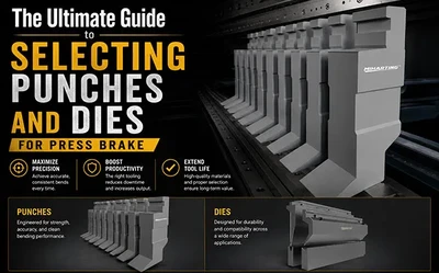 The Ultimate Guide to Selecting Punches and Dies for Press BrakeJune 1, 2026Bending tools—press brake punches and dies—serve as the "teeth" of metal fabrication; they directly determine both the precision of the finished product and the service life of the machine tool. In this article, we will guide you through a systematic approach to selecting the most suitable tooling, examining four key dimensions: material, geometry, V-die selection, and compatibility.view
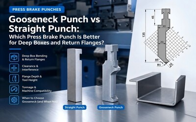 Gooseneck Punch Vs Straight Punch: Which Press Brake Punch Is Better for Deep Boxes and Return Flanges?September 18, 2026When a press brake part includes a deep box, tall return flange, or several bends close together, choosing a punch based only on angle and radius can lead to interference during forming. The critical ...view
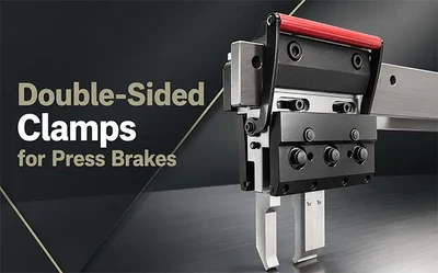 Double-Sided Clamps: The Smarter Way to Expand Press Brake Bending FlexibilityJune 23, 2026Discover how FAST double-sided clamps help press brake users achieve front and rear tool clamping, faster setup, safer operation, and lower tooling costs.view