EN
EN

A tooling catalogue is useful only when it helps an engineer move from a part drawing to a safe, repeatable bending setup. Buyers often start with a machine brand and a familiar tool description, but compatibility depends on more than the name on the press brake. The upper-tool tang, lower-tool seat, clamping method, usable tool height, working length, sectional arrangement, maximum load and part-clearance requirements must work together. A catalogue that lists only profile pictures and item codes may be convenient for browsing, yet it is not enough for a production decision.
This guide explains how procurement teams, production engineers and press brake supervisors can evaluate tooling for Bystronic-style systems without confusing “compatible tooling” with an original-equipment claim. MIHARTING is an independent press brake tooling manufacturer. Final compatibility should always be confirmed against the exact machine model, clamping system, existing tool drawings and bending application before an order is released.
A Bystronic press brake tooling catalogue is a structured reference used to match punches, dies, adapters and segments with a specific press brake interface and bending requirement.
A useful catalogue should connect the machine interface to the workpiece requirement. At minimum, it should identify the tool family, tang or holder geometry, overall and usable height, working angle, nose radius, die opening, die shoulder radius, section lengths, permissible load and available surface treatment. It should also distinguish standard profiles from made-to-drawing profiles. This distinction matters because a tool can appear dimensionally similar while differing in a critical locating surface, safety groove, load-bearing shoulder or clamping feature.
For a first-pass selection, the catalogue can narrow the options. For purchase approval, the buyer should request a dimensioned drawing and compare it with the press brake manual, the existing tool sample or a verified holder drawing. This two-stage process prevents a common purchasing error: ordering by brand-style name alone and discovering during installation that the tang, tool height or clamp engagement does not match the machine.
The machine interface is the set of physical dimensions and clamping features that locate, support and retain the tooling in the press brake.
Record the complete press brake identification before selecting a tool. The machine model, year, tonnage, bending length and clamping configuration are more useful than a general statement such as “we use a Bystronic brake.” Machines can be retrofitted, clamps can be replaced and factories sometimes operate mixed tooling systems across several brakes. A machine may therefore carry one brand name while using a clamping interface that differs from the buyer’s assumption.
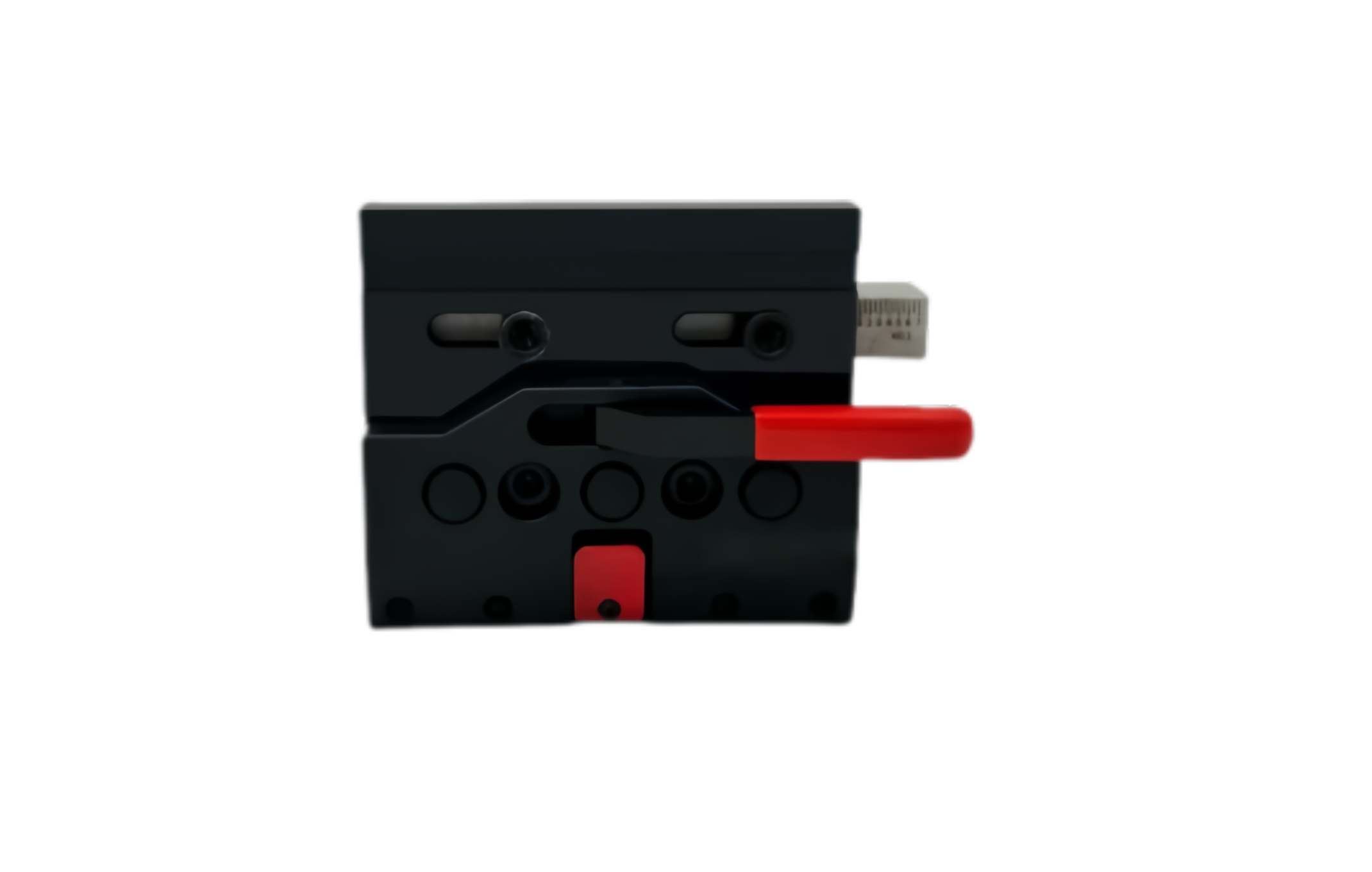
For the upper tool, measure or document the tang thickness, tang height, locating shoulder, safety groove, tool centerline and the way the clamp applies force. For the lower tool, verify the die seat width, locating method, centerline, adapter arrangement and whether the die is loaded directly or through a holder. When possible, send photographs with a scale, a drawing of the holder and the dimensions of a known tool that fits correctly.
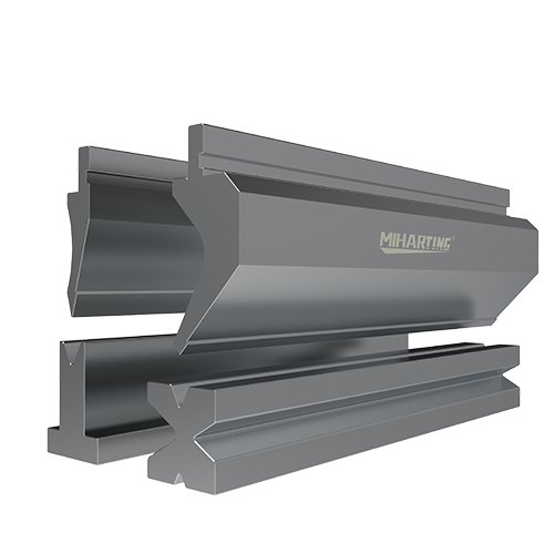
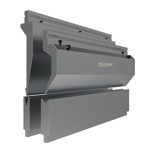
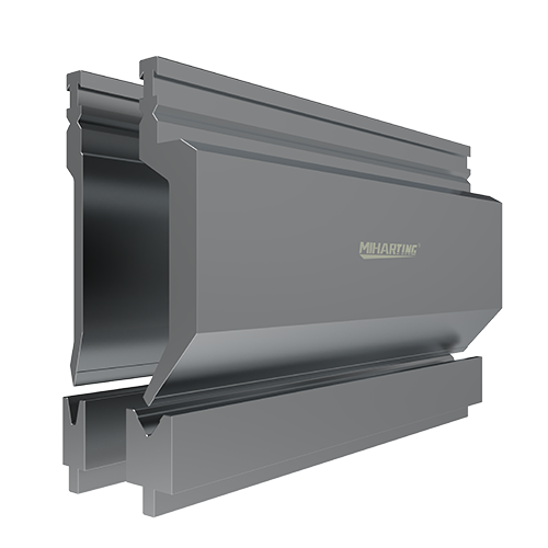
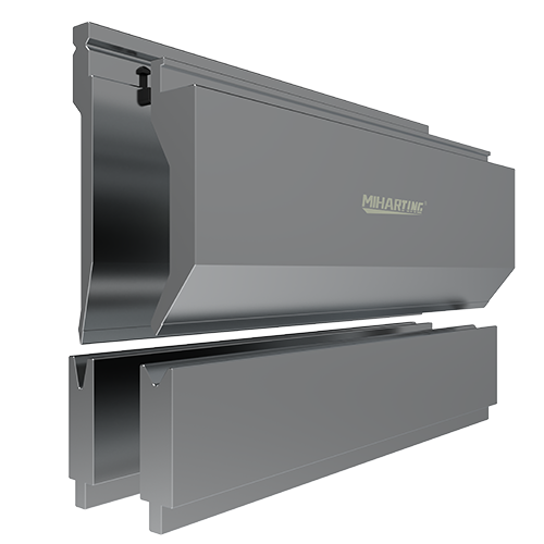
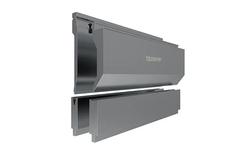
MIHARTING’s bystronic press brake tooling range should be treated as a compatibility family rather than a substitute for dimensional verification. A proper quotation should state the proposed interface and include an approval drawing, especially when the order includes long tools, high-load profiles, special safety features or a combination of standard and custom segments.
A catalogue becomes easier to use when its fields are reviewed in the sequence that determines the bend: material, geometry, force, clearance, interface and segmentation.
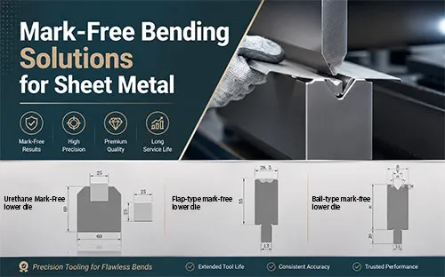
Begin with the workpiece. Record material grade, tensile strength or a reliable strength range, thickness, bend length, required inside radius, angle, flange lengths, surface sensitivity and annual quantity. The same nominal thickness can require a different setup when the material changes from mild steel to stainless steel or high-strength steel. Surface-finished stainless, pre-painted sheet and visible aluminum panels also introduce marking constraints that may justify a larger shoulder radius, protective film or rolling-die solution.
Next, identify the bending method. Air bending is flexible because one punch-and-die combination can produce multiple angles by controlling penetration depth. Bottom bending provides stronger geometric control but requires closer agreement between punch, die and target angle. Coining uses substantially higher pressure and is less common in modern general fabrication. The intended method changes the correct V-opening, required force and expected inside radius, so it should never be omitted from the request for quotation.
Only after these process variables are known should the buyer select the interface, tool profile and section plan. This prevents the catalogue from becoming a visual shopping list. A technically sound selection works backward from the finished part and then verifies that the selected tooling can be safely installed on the available machine.
The V-opening is the width of the lower-die opening that supports the sheet and strongly influences bending force, minimum flange and naturally formed inside radius.
A widely used starting point for air bending mild steel is the “rule of eight,” meaning that the V-opening is approximately eight times the sheet thickness. For example, 2 mm mild steel begins with a V-opening near 16 mm, while 3 mm material begins near 24 mm. This is a starting rule, not a universal specification. Thin material, short flanges, stainless steel, aluminum, high-strength steel, a large target radius or a surface-sensitive part can require a different ratio.
A smaller V-opening usually produces a smaller inside radius and supports a shorter flange, but it raises the required force and increases local contact pressure. A larger opening lowers force and can reduce concentrated marking, but it increases the natural radius and minimum flange. The correct choice therefore balances geometry, tonnage, tool rating and appearance rather than optimizing one variable in isolation.
Catalogue tables should state the V-opening, die angle, shoulder radius, die height and maximum load. When the application is not standard, ask the supplier to show the selection logic and the expected force per meter. The buyer should then verify the result against the press brake’s available tonnage, the tool’s rated load and the actual bend length. Never assume that a high-tonnage machine makes an undersized die safe.
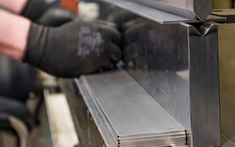
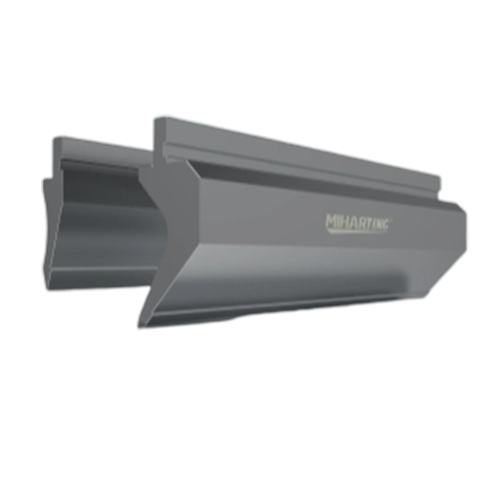
A press brake punch is the upper tool that applies force to the sheet and defines the contact geometry, clearance envelope and part-access limits during bending.
Punch selection starts with the target inside radius and the part profile. A straight punch provides a direct load path and is often preferred when the part offers sufficient clearance. A gooseneck punch creates return-flange clearance for boxes and channels, but its offset shape can reduce allowable load compared with a straight profile of similar size. Acute punches support pre-bending, hemming sequences and tighter angular work, while radius punches are used when the drawing requires a larger formed radius.
The punch nose radius should support the bending method and material without creating excessive indentation. In air bending, the naturally formed radius is influenced strongly by the V-opening and material characteristics; the punch radius still matters because an extremely sharp nose can concentrate stress and mark the sheet. In bottoming, punch and die geometry have a more direct relationship with the final profile.
When comparing catalogue options, review the profile drawing rather than the marketing name. The drawing should show the nose radius, working angle, total height, tang, load-bearing section and the interference envelope. Use the part’s folded geometry to check whether the side wall, return flange or previously formed bend will collide with the punch body or clamp. The MIHARTING press brake punches page can serve as an internal product reference, but the final choice should be linked to a dimensional clearance review.
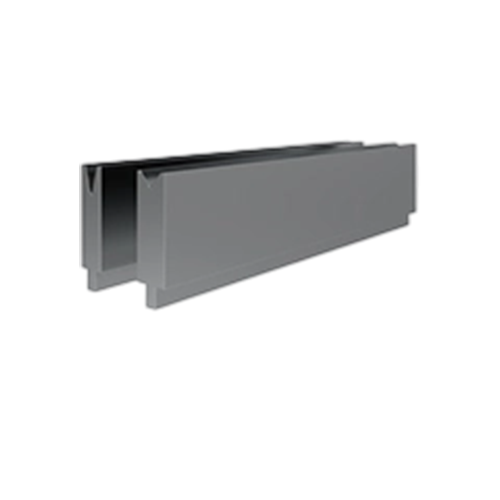
A press brake die is the lower tool that supports the sheet, establishes the bending opening and carries the reaction load during forming.
Single-V dies are efficient when a production cell uses a stable range of materials and thicknesses. Multi-V dies place several openings on one body and can reduce changeover frequency, although the operator must rotate and locate the correct opening. Adjustable or variable-opening dies can support heavier plate and a broader thickness range, but the mechanism, load rating and opening repeatability must be suitable for the application. Rolla-V or roller-style dies may reduce drag and marking for particular parts, especially when surface quality and short flanges are important.
The die shoulder radius affects contact pressure and material movement. Sharp or damaged shoulders can create witness lines. The die angle must also provide sufficient clearance for the intended bend angle and account for springback. For acute work, the die and punch combination should be reviewed as a system, not selected independently.
Catalogue comparisons should include V-opening, angle, shoulder radius, total height, usable height, base width, seating detail, rated load and available lengths. Buyers evaluating press brake dies should also ask whether the quoted load is expressed per meter, per foot or for the complete segment, because confusing these units can create a serious safety and equipment risk.
Bending tonnage is the force required to form the specified material over the stated bend length with the selected tooling geometry.
Tonnage should be calculated using a recognized force chart, machine software or supplier calculation based on material strength, sheet thickness, bend length and V-opening. Force rises rapidly with thickness and generally falls as the V-opening becomes larger. Stainless steel and high-strength materials commonly require a higher force allowance than ordinary mild steel of the same thickness.
The result must pass three separate checks. First, the machine must have sufficient available force over the required length. Second, the punch, die, holder and adapter must each be rated for the calculated line load. Third, the load distribution must be compatible with the segment arrangement and machine setup. A short, heavily loaded segment can be more critical than a long bend with the same total tonnage because the force is concentrated over less length.
Use consistent units throughout the calculation. A catalogue may state metric tons per meter, kilonewtons per meter or tons per foot. Convert before comparing. Keep a documented safety margin rather than operating at the exact published limit, and reduce the allowable load when the tool is modified, damaged, heavily reground or used in a nonstandard arrangement. The machine manufacturer’s instructions and the approved tool drawing take precedence over generic rules.
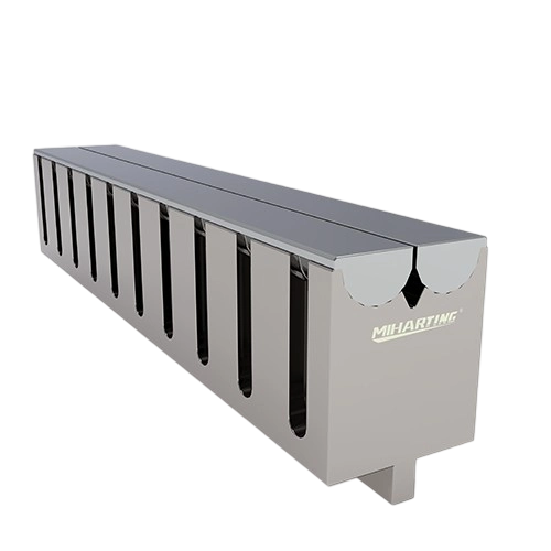
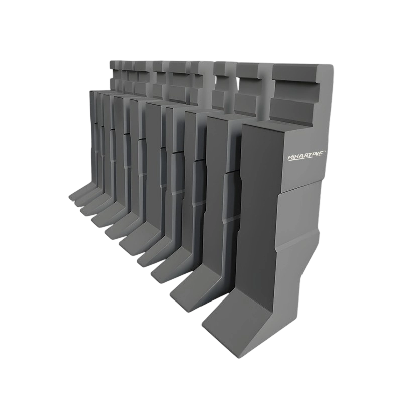
Tool segmentation is the division of a punch or die into standardized lengths so operators can build the required working length and create clearance for boxes, tabs and partial bends.
A practical segment set normally combines long pieces for straight runs with shorter pieces for fine adjustment and end access. The exact set should reflect the factory’s part mix. A shop producing electrical cabinets may need flexible short segments and horn pieces, while a long-panel producer may prioritize alignment and continuity across longer sections.
Catalogue listings should identify each segment length, its location in the set and whether the profile is reversible. Confirm how the segments are marked and whether the total nominal length includes kerf or fitting allowance. Ask the supplier about height matching across the set, because even small inconsistencies can create angle variation or visible transitions in a long bend.
For high-mix production, the best segment plan is not necessarily the largest set. It is the smallest arrangement that covers the recurring bend lengths and clearance conditions without excessive handling. Review twelve months of job history, group common bending lengths and note which parts require local tool gaps. This evidence-based method reduces unnecessary inventory and makes the catalogue selection easier to defend internally.
Standard tooling uses established catalogue profiles, modified tooling adapts a standard platform, and fully custom tooling is designed around a specific part or process constraint.
| Decision Factor | Standard Catalogue Tooling | Modified Standard Tooling | Fully Custom Tooling |
|---|---|---|---|
| Best use | Common angles, radii and open profiles | Special length, relief, coating or local clearance | Unique form, severe interference or high-volume dedicated part |
| Engineering effort | Low after interface verification | Moderate; drawing approval required | High; part simulation and process review recommended |
| Lead-time tendency | Usually shortest when stock or semi-finished blanks exist | Longer because machining or treatment is added | Longest because design, validation and manufacturing are application-specific |
| Change flexibility | High across many jobs | Medium | Low unless designed as a modular solution |
| Primary risk | Assuming brand-style compatibility without checking dimensions | Changing a profile without recalculating load | Freezing an unproven process into an expensive dedicated tool |
Choose standard tooling when the part can be produced safely with a proven profile. Choose a modified standard when one controlled change solves the problem without altering the fundamental load path. Choose a fully custom tool when the geometry, material, volume or quality requirement justifies engineering a dedicated solution. In all three cases, an approved drawing and a stated load rating are essential.
Tool material and heat treatment determine the balance among strength, toughness, wear resistance, grindability and resistance to permanent deformation.
Do not accept a single universal material claim for every tool. A long general-purpose punch, a high-load die, a replaceable insert and a delicate roller component can require different material and treatment decisions. MIHARTING’s website references alloy tooling steels and precision grinding, but the quotation should state the actual material, hardened zone, hardness range, surface treatment and dimensional tolerance for the ordered profile.
Hardness alone is not a complete quality measure. Excessive hardness with inadequate toughness can increase chipping risk, while insufficient hardness can accelerate wear and loss of geometry. The depth and location of hardening matter because the working surface must resist wear while the body continues to carry bending load. Surface treatments such as nitriding or hard chrome can improve wear or friction behavior in selected applications, but they do not correct poor base geometry or an unsuitable material choice.
Accuracy should be described by measurable features. Ask for tolerances on tool height, straightness, working angle, nose radius, V-opening, centerline and segment matching. For long sets, request the inspection method and reference length. A generic phrase such as “high precision” is less useful than a drawing with tolerances and a final inspection report.
A tooling RFQ data sheet is a controlled list of machine, material, part and commercial information that allows the supplier to select or design the correct tool without repeated assumptions.
Press brake manufacturer, exact model, year, tonnage and bending length.
Upper and lower clamping system, holder drawings and photographs.
Existing compatible tool drawing or a sample profile, when available.
Material grade, thickness range, tensile strength and surface condition.
Part drawing in PDF and a neutral CAD format, including bend sequence if known.
Required inside radius, angle tolerance, flange lengths and visible-surface requirements.
Bending method, annual volume, batch size and expected changeover frequency.
Preferred segmentation, total working length and special end pieces.
Required surface treatment, marking, packing and inspection documents.
Destination, target delivery date and any import or compliance documentation.
Send the RFQ data in one package and identify which items are confirmed versus provisional. This reduces quotation cycles and allows engineering questions to be resolved before price becomes the only comparison. For a repeat order, include the previous approved drawing and note any observed wear, marking, setup or angle-control issue.
A tooling acceptance plan defines the measurements, trial bends and documentation required before the tool is released for routine production.
Start with incoming inspection. Check tool identification, quantity, segment lengths, visible damage, corrosion protection and packaging condition. Measure critical interface and working dimensions against the approved drawing. For a segmented set, assemble the required length and check height consistency, centerline and joint condition.
Then conduct a controlled trial bend with a documented material lot. Record machine, program, V-opening, tool segments, bend length, material thickness, target angle, measured angle, inside radius and surface result. Run more than one piece so repeatability can be observed. If the application is long or high-load, measure results at several positions along the bend and confirm that crowning or compensation settings are appropriate.
Acceptance should separate tool quality from process variables. Springback, material thickness variation, grain direction and machine deflection can affect the result even when the tool is within tolerance. When a deviation appears, compare the tool drawing, setup, material certificate and machine condition before assigning the cause.
Total tooling cost includes purchase, engineering, setup, scrap, maintenance, storage, downtime and the financial effect of inconsistent bends.
A lower-priced tool can be expensive if it needs repeated shimming, creates marks on visible parts, requires excessive trial bends or arrives without usable drawings. A premium tool is not automatically the best choice either; paying for a complex custom profile is wasteful when a standard punch and die can produce the part safely. Compare the options using the expected number of setups, annual bend volume, scrap value, labor rate and cost of machine downtime.
Use an illustrative decision model. Suppose one tooling option saves six minutes per setup, the cell completes eight setups per day and the loaded labor-and-machine cost is $90 per hour. The theoretical time value is 0.1 hour × 8 × $90, or $72 per day before considering utilization and other constraints. This is not a guaranteed saving; it shows why setup behavior should be included in the purchase decision. Replace the example values with the factory’s actual data.
Also consider replacement risk. A supplier that retains approved drawings, material records and inspection data can make repeat orders more predictable. Standardized labels and segment lists reduce the chance that production receives a different configuration years later.
MIHARTING supports tooling projects by reviewing machine-interface data, part requirements, tool geometry and manufacturing documentation before production.
The most effective inquiry includes the machine model, holder dimensions, material range, part drawings and the problem the buyer is trying to solve. That problem may be excessive marking, insufficient flange clearance, high bending force, long setup time, unavailable legacy tooling or the need to standardize several press brakes. Engineering should then propose a standard profile, a controlled modification or a custom solution with a clear reason for the choice.
Ask for an approval drawing, stated material and treatment, load rating, segmentation plan, inspection items and packing method. For brand-style tooling, the documentation should describe compatibility without implying that MIHARTING is the original machine manufacturer. This transparent wording helps procurement teams compare independent tooling suppliers while protecting technical accuracy.
The following questions address common catalogue, compatibility and purchasing issues for Bystronic-style press brake tooling.
The model is a useful starting point, but it is not enough for every order. Confirm the upper and lower interface, clamp type, tool height and any retrofit history. A holder drawing or correctly fitting sample reduces risk.
For mild steel, eight times material thickness is a common starting point. The final opening should account for material strength, thickness, minimum flange, target radius, force, surface marking and the available die set.
No universal assumption should be made. Machine generation, clamping system, retrofit components and regional configurations can differ. Verify dimensions and approve the supplier drawing before production.
Segmented tooling offers greater flexibility for boxes, short bends and mixed lengths. Longer pieces can improve setup speed and continuity for recurring long parts. Many factories use a balanced set containing both.
Request an approved manufacturing drawing, material and heat-treatment statement, load rating, dimensional inspection report, segment list, packing list and any agreed compliance documents.
Review die shoulder condition, V-opening, protective film, tool cleanliness, surface treatment and rolling-die options. Use a controlled trial because reducing marks can change force, radius or minimum-flange behavior.
A Bystronic press brake tooling catalogue should function as an engineering decision tool, not merely a product gallery. The safest process begins with the exact machine interface, then connects material, bend geometry, V-opening, punch clearance, die selection, tonnage and segmentation. Standard profiles should be preferred when they solve the application; modified or custom tools should be justified by a measurable constraint.
For a faster and more accurate MIHARTING quotation, provide the press brake model, clamp and holder details, material range, part drawings, bend length, quality requirements and preferred segment plan. Request a dimensioned approval drawing and a documented load rating before the order is released.
These external sources provide independent technical and safety context for press brake tooling selection.
https://www.bystronic.com/usa/en-us/news/190502-rules-press-brake-tool-selection — Bystronic, rules of press brake tool selection.
https://www.trumpf.com/en_US/solutions/applications/bending/ — TRUMPF, bending processes and methods.
https://www.osha.gov/laws-regs/regulations/standardnumber/1910/1910.212 — OSHA, general machine-guarding requirements.
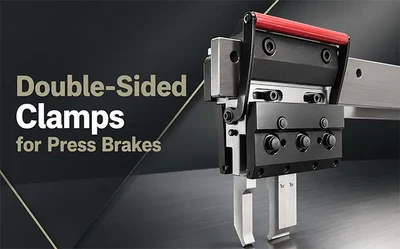 Double-Sided Clamps: The Smarter Way to Expand Press Brake Bending FlexibilityJune 23, 2026Discover how FAST double-sided clamps help press brake users achieve front and rear tool clamping, faster setup, safer operation, and lower tooling costs.view
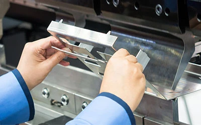 Press Brakes Don't Just Bend Metal - They Bend the RulesJuly 25, 2025The Basics and Trends of Sheet Metal Manufacturing IndustrySheet metal remains the backbone of countless industries, from automotive frames to aerospace components.view
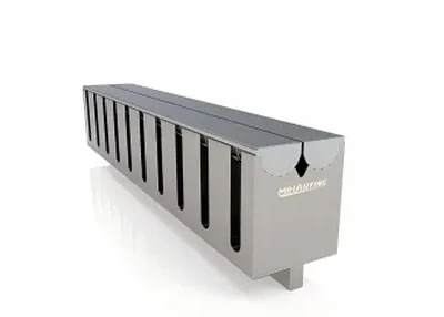 Rolla-V Tooling: The Ultimate Solution for Mark-Free Bending and Short Flange ChallengesApril 22, 2026In the traditional air bending process, the sheet metal slides over the shoulders of a static V-die. This movement creates friction, resulting in “die marks” or “witness marks” on the underside of...view
 What Special Requirements Do Titanium Alloys and Composite Materials Have for the Design of Bending Machine Molds?June 26, 2025Titanium Alloy:1. Due to the high hardness of titanium alloys, mold design needs to consider the use of specially designed structures and processes to adapt to its bending characteristics. The choice ...view
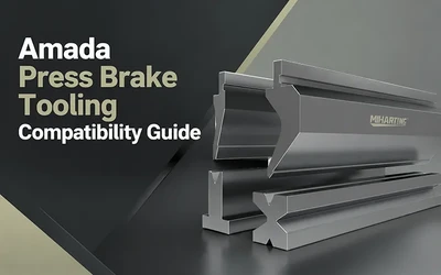 Amada Press Brake Tooling Compatibility GuideJune 18, 2026Learn how to choose compatible Amada press brake tooling for European machines. Avoid wrong interfaces, poor fit, and short tool life with 42CrMo, HRC 48-52, full length heat treatment tooling.view
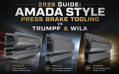 2026 Guide: Amada Style Press Brake Tooling vs Trumpf & WilaMay 26, 2026In this guide, we will focus on analyzing the advantages of Amada press brake tooling and compare it with its competitors.view