EN
EN

An LVD press brake can remain productive for many years, but tooling decisions become more complicated when a factory adds new materials, inherits mixed tool sets, changes clamping systems or buys replacement tools from an independent supplier. The machine name alone does not guarantee that a new punch or die will fit, lock correctly and produce the required part. The practical question is not “Is this LVD tooling?” It is “Does this exact tooling interface, geometry and load rating match this exact press brake and this exact bending process?”
This guide uses a diagnostic workflow rather than a catalogue-style product list. It helps maintenance managers, process engineers and buyers determine whether an existing setup needs a direct replacement, an adapter, a new clamp, a revised segment set or a custom tool. MIHARTING manufactures compatible press brake tooling independently and is not the original machine manufacturer. All dimensions and load limits should be confirmed through drawings, machine documentation and controlled trial bends.
LVD press brake tooling is compatible when its upper and lower interfaces, working height, centerline, load capacity and geometry match the machine, clamping system and bending application.
Compatibility has three layers. Mechanical compatibility means the tool physically locates and locks in the holder or clamp. Process compatibility means the punch, die and opening can form the material and part geometry within the available force and clearance. Operational compatibility means the tooling can be handled, segmented, stored and changed safely in the factory’s normal workflow.
A tool can pass the first layer and still fail the other two. For example, a punch may fit the clamp but collide with a return flange. A die may sit correctly but require more force than the machine or tool can safely carry. A segmented set may form the part but take too long to assemble because it does not match recurring bend lengths. A complete review therefore follows the bending process from machine interface through production use.
The press brake configuration is the verified combination of machine model, tonnage, bending length, ram or beam arrangement, holders, clamps, adapters and control features currently installed.
Begin by photographing the machine nameplate, upper clamp, lower holder and one known tool that fits correctly. Record the model, serial number, approximate year, nominal tonnage and working length. Then note any retrofit history. A machine may have received a different clamp, quick-clamping system, hydraulic holder, crowning unit or adapter long after it left the original factory.
Measure the features that determine location and retention. For the upper interface, include tang thickness, tang height, shoulder position, safety groove, centerline and clamp contact area. For the lower interface, include base width, seat profile, locating key, holder opening and adapter stack. Measure overall and usable height of the known tool and note the shut-height or daylight constraints of the press brake.
This documentation creates a reference package that can be reviewed by a supplier before a quotation is issued. It also protects the factory from relying on memory. If several LVD brakes operate on the same floor, create a separate interface sheet for each machine and identify which tool families can be shared.
The upper-tool interface is the tang, shoulder and retaining geometry through which the clamp positions and secures the punch.
Check whether the clamp loads the tool through a defined shoulder, wedge, hydraulic mechanism, manual screws or an adapter. The tool must seat consistently along the working length. A tang that is slightly too thick may appear to enter the clamp but prevent full engagement. A tang that is too thin can shift, tilt or depend on improvised shims. A missing or incorrectly positioned safety feature can also create a handling hazard.
Inspect the clamp itself. Dirt, burrs, worn wedges, damaged contact surfaces and uneven hydraulic pressure can create alignment problems that are incorrectly blamed on new tooling. Before replacing a complete set, clean and measure the clamping surfaces and compare results across the machine.
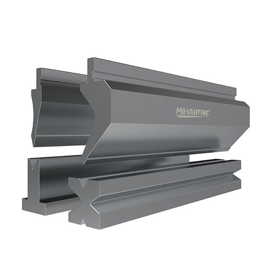
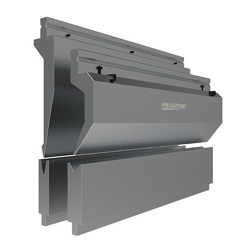
When evaluating MIHARTING lvd tooling, request a dimensioned tang drawing and compare it with both the machine documentation and a verified sample. Do not approve a purchase solely from a profile photo. State whether the tool will be loaded vertically or horizontally, because handling and safety features can differ by system.
The lower-tool seat is the holder or adapter surface that supports and centers the die under bending load.
A lower die must sit flat and align with the punch centerline. Check the base width, locating groove, adapter geometry and the method used to secure or position the die. A mismatch can shift the V-opening away from the machine centerline, creating unequal shoulder contact and inconsistent angles. It can also concentrate load on a small area of the holder.
Use an indicator, alignment bar or approved machine procedure to verify punch-to-die alignment at several points along the bed. If alignment changes from left to right, investigate the holder, clamp, ram, bed and crowning condition before ordering a special die to compensate for a machine problem.
Adapters can be useful when a factory wants to share a tooling family across machines, but every adapter adds height and another interface. Confirm daylight, stroke, rigidity, load rating and centerline after the complete stack is assembled. The adapter should be documented as part of the tooling system rather than treated as an incidental accessory.
The bending method defines how deeply the punch enters the die and how the sheet contacts the tooling during angle formation.
Air bending forms the angle by controlling punch penetration while the sheet contacts the punch and the two die shoulders. It offers flexibility because one setup can produce multiple angles. Bottom bending brings the sheet into fuller contact with the die geometry and normally requires a more specific punch-and-die relationship. Coining forces the material into the tool at much higher pressure and should not be assumed safe merely because the machine has enough total tonnage.
The method affects springback, force, inside radius and tooling choice. If an older LVD program was built around bottoming but the factory wants to move to air bending, the V-opening, punch radius, ram depth and angle-compensation strategy must be reviewed together. Conversely, replacing an old bottoming tool with a general air-bending set may change the resulting radius and flange behavior.
Document the current method with actual setup data. Record the punch, die, V-opening, material, thickness, bend length, ram position and measured result. This evidence makes it easier to decide whether a tooling change is solving a process limitation or simply introducing a new variable.
The V-opening is the lower-die opening that governs the support span, required force, minimum flange and much of the naturally formed radius in air bending.
For ordinary mild-steel air bending, a V-opening near eight times material thickness is a common starting point. The ratio may be adjusted for thin sheet, stainless steel, aluminum, high-strength steel, larger radii, short flanges or marking concerns. A smaller opening supports a shorter flange and smaller radius but requires more force. A larger opening reduces force but increases radius and minimum flange.
Calculate the force with a recognized bending chart, machine software or a supplier’s documented method. Use the actual bend length and material strength. Then compare the result with the machine capacity and every component in the load path: punch, die, holder, clamp, adapter and crowning system. The weakest rated component controls the allowable setup.
Do not mix units. Tool catalogues may use metric tons per meter, kilonewtons per meter or tons per foot. Convert before comparing. For short segments, review concentrated line load rather than total machine tonnage. A 200-ton press brake does not make a lightly rated 100 mm tool segment safe under a heavily concentrated bend.
Punch geometry is the shape of the upper tool body and nose that determines load path, access and clearance around previously formed flanges.
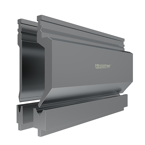
A straight punch is generally strong and simple when the part has open clearance. A gooseneck punch provides space for return flanges, channels and boxes, but its offset profile must be checked for both interference and rated load. Acute punches can support pre-bending and hemming sequences. Radius punches create larger formed radii when the drawing requires them.
Build a clearance sketch using the finished or intermediate part profile. Include the clamp, punch body, die shoulders and adjacent bends. Check every step in the bending sequence rather than only the final bend. Many collisions occur because a return flange formed in an earlier operation enters the punch body during a later operation.
When the part family is stable, a custom relief or special gooseneck can solve a recurring interference problem. When the part mix is broad, a standard modular set may provide better flexibility. MIHARTING’s general press brake tooling range can be used to compare profile families, but the release decision should be based on a part-specific clearance review.
The die type determines how the sheet is supported, how openings are changed and how the lower tool fits the shop’s mix of materials and part sizes.
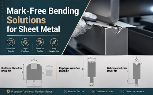
A single-V die offers a dedicated opening with straightforward setup and inspection. It is effective for stable production ranges. A multi-V die provides several openings on one body and can reduce the number of separate dies, but it must be rotated and positively located. Adjustable V-dies support heavy plate and changing openings, although their mechanism and repeatability need careful review. Roller or Rolla-V-type dies can reduce drag and surface marking in selected applications.
Choose the die based on recurring work, not the widest theoretical capability. Review the thickness distribution of jobs completed over the last six to twelve months. Identify the openings used most often, the parts with short flanges, the materials with visible surfaces and the jobs that approach machine or tool limits.
For each candidate die, compare V-opening, shoulder radius, angle, height, base width, load rating, segment lengths and handling weight. If operators must rotate a heavy multi-V body manually, include the lifting method and changeover procedure in the decision.
A segment set is a planned collection of tool lengths that can be combined to build long straight runs, short local bends and clearance gaps.
Segment planning should start with job history. List common bend lengths and identify parts that require end relief, horn sections or a gap around a tab. Then select a balanced set of long, medium and short pieces. Too many small segments increase assembly time and joint count. Too few segments reduce flexibility and may force operators to use an unnecessarily long setup.
Check how segments are marked. Each piece should carry a profile ID, length and set reference that remains readable after routine cleaning and handling. Height matching across the set is critical. If adjacent pieces differ, a long part can show angle changes or visible transition lines.
For shared tooling, standardize the segment logic across compatible machines. A common naming and storage system allows operators to locate the correct pieces quickly and reduces the chance of mixing similar but nonidentical profiles.
A structured troubleshooting process isolates whether a bending defect originates in the tooling, machine, material, program or handling method.
| Observed Problem | Possible Tooling Cause | Possible Non-Tooling Cause | First Verification |
|---|---|---|---|
| Angle varies along the bend | Height mismatch, worn die shoulders, misaligned segments | Crowning, ram parallelism, bed deflection, material variation | Measure tool height and run a controlled bend at multiple positions |
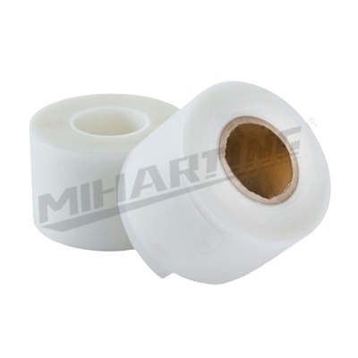
| Part is marked | Damaged shoulder, small V-opening, dirty tool, sharp contact radius | Contaminated material, handling scratches, unsuitable protective film | Clean the setup and compare a known material sample |
| Punch will not clamp evenly | Incorrect tang, burr, damaged locating surface | Worn clamp, uneven hydraulic pressure, debris in holder | Measure tang and inspect clamp contact along the beam |
| Return flange collides | Insufficient gooseneck clearance or wrong punch body | Incorrect bend sequence or part orientation | Review the complete intermediate part profile |
| Required force is excessive | V-opening too small, wrong bending method | Material strength higher than assumed, thickness out of range | Verify material certificate, thickness and selected opening |
Use one controlled change at a time. Replacing the punch, die, program and material simultaneously may produce a good part but does not reveal which change solved the problem. A documented troubleshooting sheet becomes valuable evidence for future tooling purchases.
A tooling-system decision compares direct replacement, adapter use and clamping-system upgrade against safety, flexibility, setup time and lifecycle cost.
Direct replacement is appropriate when the existing interface is sound, tooling is readily available and the factory wants minimal process change. An adapter can connect two tooling standards and support sharing, but it adds height, interfaces and load considerations. A clamp upgrade may reduce changeover time and expand tooling options, yet it requires capital, installation planning and verification of machine geometry.
| Option | Advantages | Limitations | Best Fit |
|---|---|---|---|
| Direct replacement | Lowest process disruption; familiar setup | May preserve an obsolete or limited interface | Stable machine, available tooling, predictable part mix |
| Adapter | Allows controlled use of another tooling family | Adds stack height, centerline and load checks | Occasional cross-system use or phased standardization |
| Clamp upgrade | Can improve speed, alignment and future availability | Higher cost; requires installation and validation | High setup frequency, long machine life remaining |
| Machine-specific custom tooling | Solves unique geometry or legacy-interface problems | Lower flexibility and replacement dependence | High-value recurring part or unavoidable legacy constraint |
Quantify the decision. Count monthly setups, average minutes per change, annual downtime, number of machines that could share tools and the cost of maintaining duplicate inventories. The option with the lowest purchase price may not have the lowest five-year operating cost.
Press brake accessories are supporting components such as clamps, adapters, backgauges, crowning systems, protective films and storage equipment that affect tooling accuracy and workflow.
A tooling upgrade can underperform when surrounding accessories are ignored. A new precision punch cannot compensate for a damaged clamp. A carefully selected die may still produce angle variation when the crowning system is not set correctly. A complete segment set may remain underused when it is stored far from the machine or mixed with unidentified tools.
Review the MIHARTING press brake accessories category during the project, but include only components that solve a verified production problem. The objective is not to add equipment. It is to create a stable system in which the machine, tooling, handling and inspection methods support the same bending result.
An approval protocol defines the drawings, inspections and production tests required before new tooling becomes an accepted factory standard.
Before manufacturing, approve a drawing that shows the interface, tool height, working angle, nose radius or V-opening, segment lengths, material, heat treatment, surface treatment and load rating. Note any assumptions about material or bending method. For a special tool, include the part drawing and intended bend sequence in the approval package.
At incoming inspection, check identification, packing, visible condition and critical dimensions. Assemble the segment set and verify height consistency. Then run a controlled trial using a documented material lot. Record the machine, program, tool set, bend length, material thickness, target angle, measured angle, inside radius, flange dimensions and surface condition.
Use at least several pieces to observe repeatability. For long bends, measure results at multiple positions. Confirm that operators can load, clamp, remove and store the tooling safely. Acceptance is complete only when the tool produces the required part and fits the production workflow.
A high-quality tooling inquiry gives the supplier enough verified information to select or design the tool without relying on brand-name assumptions.
Machine model, serial number, year, tonnage and bending length.
Upper clamp and lower holder drawings or measured interface sketches.
Photographs of the machine interface and a known compatible tool.
Material grade, tensile-strength range, thickness and surface condition.
Part drawings, bend sequence, annual volume and batch size.
Required inside radius, angle tolerance, flange lengths and appearance criteria.
Preferred bending method and current setup data.
Segment lengths, total working length and clearance requirements.
Required inspection report, markings, packaging and replacement documentation.
Mark each item as confirmed, measured or estimated. Ask the supplier to identify any assumption in the quotation. This creates a cleaner technical discussion and helps procurement compare offers on the same basis.
MIHARTING approaches LVD-style tooling projects by verifying the interface, reviewing the part and process, selecting a standard or custom geometry and documenting the proposed configuration.
The most efficient project begins with the machine and part data described above. Engineering can then determine whether the requirement is a direct replacement, a new profile, a segment-set redesign or a broader clamp-and-accessory project. The proposal should explain why the selected geometry is appropriate and state the limits that matter in production.
For legacy machines, dimensional evidence is especially important. A sample tool may have been reground or modified, so measurements should be compared with the holder and clamp rather than copied blindly. When possible, retain a digital approval package for repeat orders and future troubleshooting.
These questions summarize common compatibility and upgrade issues for LVD press brake tooling.
No. Machine generation, clamp configuration, region and retrofit history can change the interface. Verify the actual holder and a correctly fitting sample before ordering.
Sometimes. The adapter must maintain centerline, rigidity and load capacity while staying within daylight and stroke limits. Validate the complete stack rather than the adapter alone.
Choose a gooseneck when return flanges or box walls would collide with a straight punch. Check the full bend sequence, clearance envelope and rated load before approval.
No. It reduces separate die inventory but can be heavy and slower to rotate. It is efficient when its openings match the actual job mix and the handling method is safe.
Possible causes include material variation, crowning, ram alignment, holder condition, segment mismatch, program depth and machine deflection. Use controlled tests to isolate the cause.
Include the interface, overall and usable height, working geometry, radii, V-opening, segment lengths, material, treatment, load rating, tolerances and identification markings.
LVD press brake tooling compatibility is a system question. The machine interface, clamp, lower seat, tool height, centerline, bending method, force, part clearance and segment plan must all agree. A direct replacement is often the simplest answer, but an adapter, clamp upgrade or custom profile can be justified when it solves a documented operational constraint.
Before requesting a MIHARTING quotation, create a verified machine-interface sheet and attach the part drawing, material data, current setup and desired outcome. The resulting proposal should include a dimensioned approval drawing and a clear load rating. This disciplined process reduces installation risk and produces a tooling set that can be repeated, inspected and maintained over its service life.
These external sources provide independent background on bending methods, force selection and press brake safety.
https://www.trumpf.com/en_US/solutions/applications/bending/ — TRUMPF, air bending and bottom bending principles.
https://wilsontool.com/en-us/resources/air-bending-force-chart — Wilson Tool, air-bending force chart resource.
https://www.osha.gov/enforcement/directives/cpl-02-01-025 — OSHA, guidance for point-of-operation guarding on power press brakes.
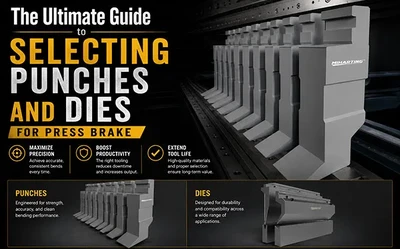 The Ultimate Guide to Selecting Punches and Dies for Press BrakeJune 1, 2026Bending tools—press brake punches and dies—serve as the "teeth" of metal fabrication; they directly determine both the precision of the finished product and the service life of the machine tool. In this article, we will guide you through a systematic approach to selecting the most suitable tooling, examining four key dimensions: material, geometry, V-die selection, and compatibility.view
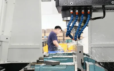 7 FAQs to Help You Quickly Choose Press Brake ToolingJune 4, 2026Unsure how to choose press brake tooling and lower die V-grooves? This article provides a detailed guide to key selection criteria for press brake dies, covering aspects such as die plate thickness, V-grooves, die segmentation, material composition, hardness, causes of die collision, and heat treatment.view
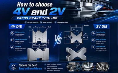 How to choose 4V and 2V press brake tooling?May 27, 2026How to choose 4V and 2V press brake tooling?What are their specific advantages,and for which applications are they best suited?This choice is a critical factor in determining your operational efficiency.We hope the following article will assist you in selecting the die best suited to your needs,thereby enhancing your production efficiency.view
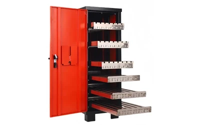 Press Brake Tooling Storage Cabinet Guide: Layout, Safety and ROI for Fabrication ShopsJuly 28, 2026Press brake tooling is precision production equipment, yet many factories store it as if it were ordinary steel stock. Punches are leaned against walls, short segments are mixed in open bins, dies are...view
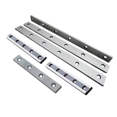
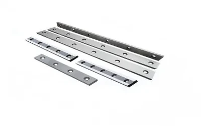 Selecting the Right Shearing Machine Blade: A Guide to Material Grades and Blade Gap OptimizationApril 22, 2026The shear is the “entry point” of the fabrication shop. If the initial cut is burred, twisted, or bowed, every subsequent process—from CNC punching to bending—will be inaccurate. MIHARTING shearin...view
 Amada Press Brake Tooling Compatibility GuideJune 18, 2026Learn how to choose compatible Amada press brake tooling for European machines. Avoid wrong interfaces, poor fit, and short tool life with 42CrMo, HRC 48-52, full length heat treatment tooling.view