EN
EN

When a 4-meter sheet bends correctly at both ends but remains more open in the center, increasing the Y-axis depth is usually not the best solution.
The problem is often press brake deflection.
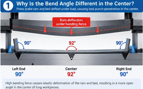
Under bending load, the ram and bed deform elastically. This reduces punch penetration around the center of the machine, producing the familiar:
90° → 91.5° → 90°
left-to-center-to-right angle pattern.
The practical solution is to first verify tooling alignment, material and machine synchronization, then use an adjustable crowning system to compensate for the machine's deflection.
Modern CNC mechanical crowning systems use precision wedge mechanisms to generate a controlled compensation curve across the bending length. The goal is not simply a higher center—it is uniform punch penetration across the entire workpiece. WILA likewise identifies ram and bed deflection as the cause of the more-open center angle, often called the “canoe effect.”
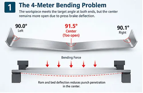
A press brake may weigh many tons, but its frame is not infinitely rigid.
During bending, force is transferred through:
Ram → Punch → Sheet → Die → Table
As bending force increases, the upper and lower beams undergo small amounts of elastic deformation.
The result is typically less punch penetration around the center of the bend.
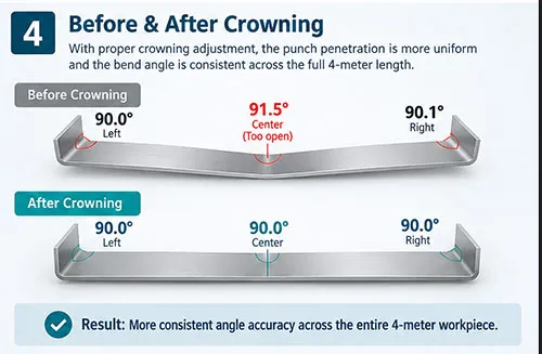
Position | Example Angle | Result |
Left | 90.0° | Correct |
Center | 91.5° | Too open |
Right | 90.1° | Correct |
This becomes more noticeable as bending length and bending force increase.
WILA explains that bending forces can deform both the ram and bed, resulting in less punch penetration in the center and therefore angular deviation along the workpiece.
Suppose your bend measures:
90° — 92° — 90°
The operator may increase Y-axis penetration.
The center improves—but the ends may now become:
89° — 90° — 89°
You have changed the overall bending depth without correcting the different penetration along the machine length.
That distinction matters.
Y-axis correction changes overall penetration.
Crowning changes penetration distribution along the bending length.
This is why long-part angle problems need to be diagnosed before simply changing the bending depth.
Not every angle error on a 4-meter part is caused by crowning.
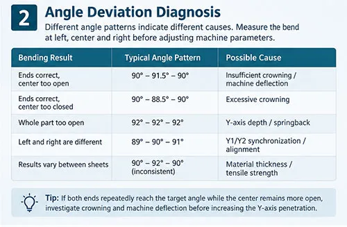
Use the angle pattern as a starting point.
Bending Result | Check First |
Ends correct, center too open | Insufficient crowning / deflection |
Ends correct, center too closed | Excessive crowning |
Whole part too open | Y-axis depth / springback |
Left and right are different | Y1/Y2 synchronization |
One local area is wrong | Tooling alignment / local adjustment |
Results vary between sheets | Material thickness / tensile strength |
If the left and right ends are correct but the center repeatedly remains open, crowning becomes one of the first areas to investigate.
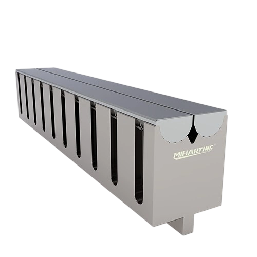
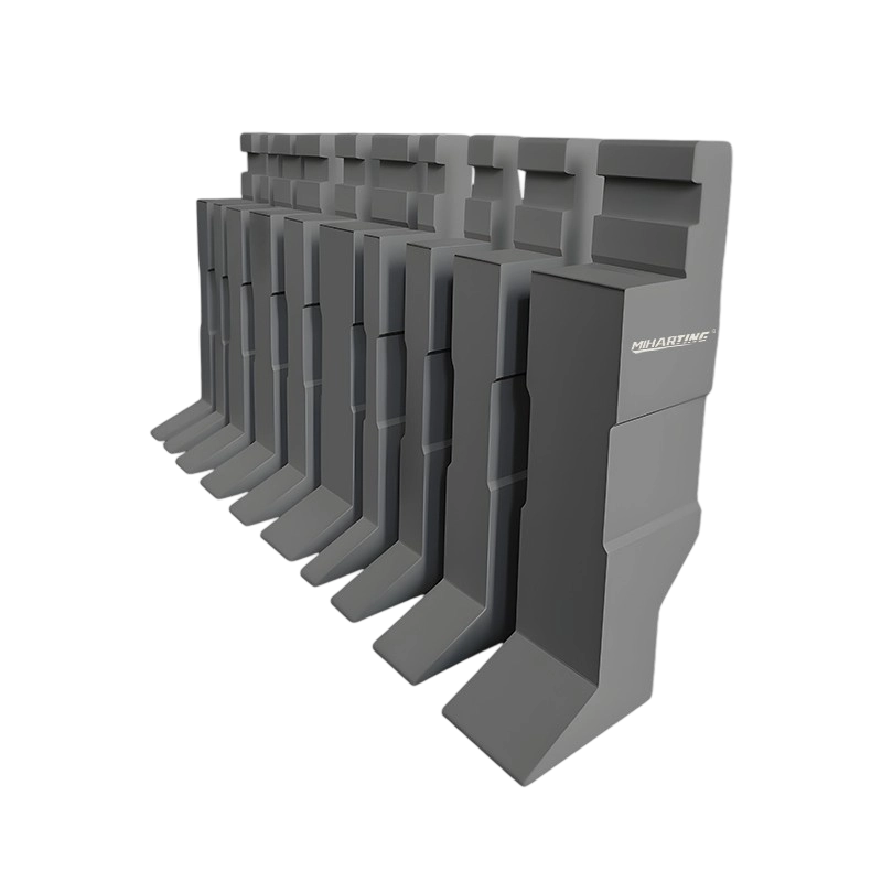
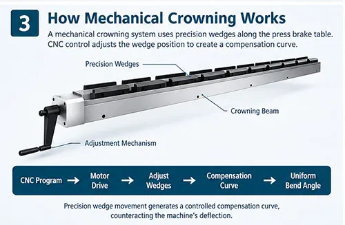
An adjustable mechanical crowning system uses a series of precision wedges along the press brake table.
Instead of leaving the lower tooling reference perfectly flat, the wedges generate a very small, controlled compensation curve.
CNC Program
↓
Crowning Value Calculated / Selected
↓
Motor Drives Wedge Mechanism
↓
Wedges Shift by Controlled Amount
↓
Compensation Curve Changes
↓
More Uniform Tool Penetration
When properly matched to the machine's deformation characteristics, this counteracts the elastic deflection created during bending.
WILA's system, for example, uses multiple adjustable Wave Wedges and states that the crowning configuration is tailored to the bending characteristics of the individual press brake rather than applying one universal compensation curve.
This term needs to be used carefully.
A customer should not interpret “micron-level crowning adjustment” as:
“Every 4-meter part is automatically guaranteed to ±0.01 mm.”
Those are different things.
Precision wedge and tool-holder systems can operate with very small dimensional adjustments, but final bending accuracy is still influenced by:
Material thickness + Tensile strength + Grain direction + Tool accuracy + Machine repeatability + Temperature + Springback + Crowning setup
For context, WILA states that its precision tool systems are manufactured to tolerances of up to ±0.01 mm, while also emphasizing alignment and crowning as separate requirements for high-precision bending.
So a better product-page claim is:
Precision mechanical wedge adjustment enables fine control of the compensation curve across long bending lengths.
This is technically safer than promising universal “micron-level finished-part accuracy.”
For 4-meter and longer precision bending, an adjustable wedge system offers several advantages.
Multiple wedges distribute compensation along the table instead of correcting only one point.
Small wedge movements produce controlled changes in vertical compensation.
Motorized systems can adjust crowning according to the bending program rather than relying entirely on manual operator adjustment.
Higher-end systems can provide local adjustment to address machine-specific deviations.
Once a proven bending program is established, the crowning setting can be reproduced for repeat jobs.
This is where many generic articles stop too early.
Even an excellent crowning system cannot compensate for every source of error.
For reliable long-part bending, five factors need to work together:
Y1 and Y2 must position the ram consistently.
Punches and dies need consistent height, geometry and straightness.
Horizontal and vertical tooling references must be correctly aligned. WILA specifically highlights Tx/Ty alignment as important for parallel flanges and consistent angles.
The compensation curve must match the actual bending condition.
Variations in thickness and mechanical properties can change springback even when the machine settings remain unchanged.
Think of long-part accuracy as a system:
Machine + Tooling + Alignment + Crowning + Material = Final Angle Accuracy
For a new long workpiece, don't immediately start changing multiple parameters.
Use a controlled sequence:
Step 1 — Confirm material and thickness
Check actual sheet thickness rather than relying only on nominal values.
Step 2 — Inspect punch and die
Make sure tooling surfaces are clean, seated and correctly aligned.
Step 3 — Make the first test bend
Do not judge the part from one measurement point.
Step 4 — Measure left, center and right
Record all three angles.
Step 5 — Identify the pattern
If both ends are correct and the center is open, evaluate crowning.
Step 6 — Adjust compensation
Increase or decrease the crowning value gradually.
Step 7 — Bend and measure again
Avoid changing Y-axis depth and crowning simultaneously unless the process requires it.
A simple pre-production checklist can prevent unnecessary trial bends:
✓ Is the actual material thickness confirmed?
✓ Is the correct V opening installed?
✓ Are punch and die surfaces clean?
✓ Is tooling fully seated in the clamp?
✓ Are Y1/Y2 correctly referenced?
✓ Is the crowning system zero/reference position correct?
✓ Are previous compensation values appropriate for this material?
✓ Will the angle be measured at left, center and right?
For repeat production, save the proven combination of tooling + material + Y position + crowning value with the bending program.
Not necessarily for every part, but crowning becomes increasingly valuable when bending long workpieces, using significant bending force or requiring consistent angles across the full bending length.
If both ends are correct, machine deflection is a likely cause. The ram and bed deform under bending force, reducing tool penetration around the center.
Neither is universally better. Mechanical systems use wedges to create the compensation curve, while hydraulic systems use cylinders integrated into the lower beam. Selection depends on machine design, required accuracy, maintenance strategy and retrofit requirements.
Not always. If the left and right angles differ significantly, first check Y1/Y2 synchronization, tooling alignment and machine geometry.
Depending on the machine design and condition, yes. Integrated mechanical crowning/tool-holder systems can be suitable for retrofit applications; interface, open height and machine condition should be evaluated first. WILA specifically notes that its integrated crowning tool holders can be fitted to existing press brakes.
When a 4-meter workpiece bends correctly at both ends but remains open in the center, don't immediately blame the operator or increase Y-axis penetration.
Start by identifying the angle pattern.
If the problem follows the classic:
90° → 91–92° → 90°
pattern, machine deflection and insufficient crowning should be investigated.
A modern CNC mechanical crowning system uses precision adjustable wedges to create the counter-deflection needed for more uniform tool penetration across the complete bending length.
But the best long-part accuracy comes from the complete system:
Stable Press Brake + Precision Tooling + Correct Alignment + Accurate Crowning + Controlled Material
If your 3-meter, 4-meter or 6-meter press brake produces different angles between the center and ends, send us:
Press Brake Model + Tonnage + Bending Length + Material + Thickness + V Opening + Left / Center / Right Angle Measurements
Miharting can help evaluate whether the problem is related to machine deflection, tooling alignment or crowning adjustment, and recommend a suitable mechanical crowning solution.
 The Sheet Metal Maestro's Playbook: A Definitive Guide to Press Brake ToolingJuly 25, 2025When Metal Meets Its Match: The Science Behind Press BrakesPress brakes don't bend metal—they persuade it.view
 How Do Aerospace Press Brake Machine Molds Cope with High Temperature and High Pressure Environments?June 25, 2025The coping strategies for aerospace press brake machine molds in high temperature and high pressure environments mainly include the following aspects:1. Select high temperature and high pressure resis...view
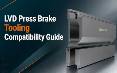 LVD Press Brake Tooling Compatibility Guide: Clamping, Segmentation and Upgrade DecisionsJuly 28, 2026An LVD press brake can remain productive for many years, but tooling decisions become more complicated when a factory adds new materials, inherits mixed tool sets, changes clamping systems or buys rep...view
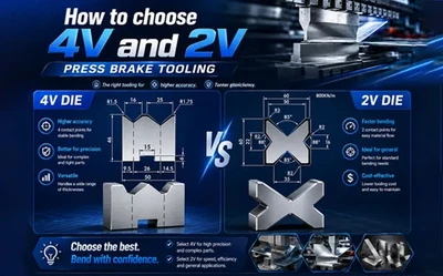 How to choose 4V and 2V press brake tooling?May 27, 2026How to choose 4V and 2V press brake tooling?What are their specific advantages,and for which applications are they best suited?This choice is a critical factor in determining your operational efficiency.We hope the following article will assist you in selecting the die best suited to your needs,thereby enhancing your production efficiency.view
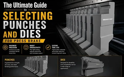 The Ultimate Guide to Selecting Punches and Dies for Press BrakeJune 1, 2026Bending tools—press brake punches and dies—serve as the "teeth" of metal fabrication; they directly determine both the precision of the finished product and the service life of the machine tool. In this article, we will guide you through a systematic approach to selecting the most suitable tooling, examining four key dimensions: material, geometry, V-die selection, and compatibility.view
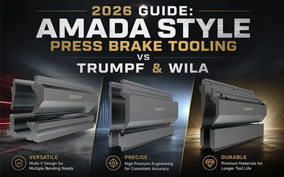 2026 Guide: Amada Style Press Brake Tooling vs Trumpf & WilaMay 26, 2026In this guide, we will focus on analyzing the advantages of Amada press brake tooling and compare it with its competitors.view