EN
 fr
 de
 es
 it
 ru
 pt
 ar
 pl

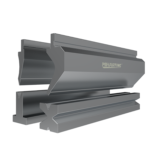
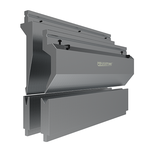
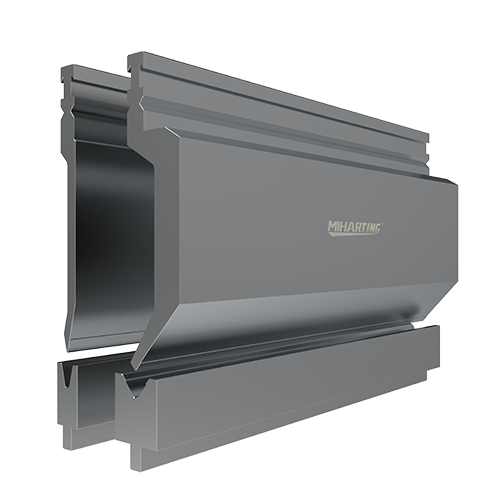
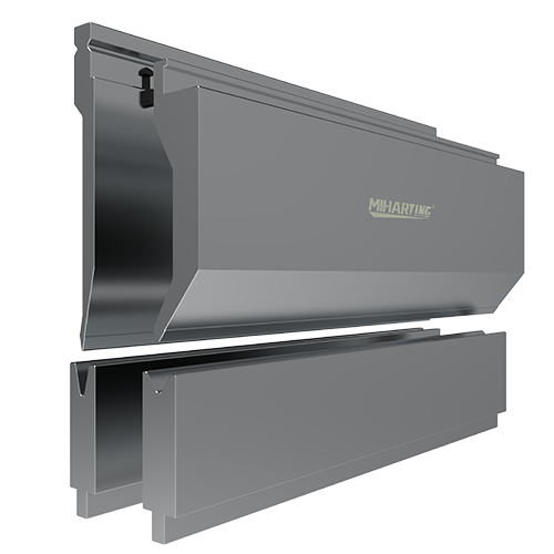
A replacement punch must match your actual clamp, tooling interface, and bending application. Providing four clear photographs along with key dimensions will help us verify the specifications before production.
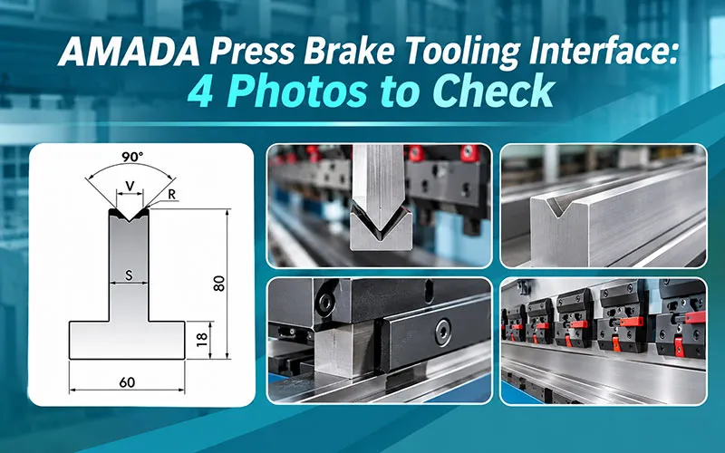
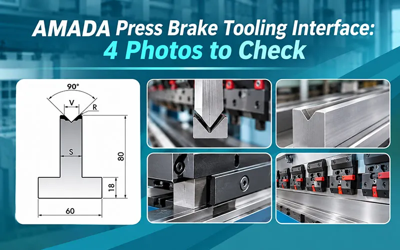
Please provide photographs showing the interface on the upper die, the machine tool fixture with the die installed, the positioning and anti-detachment mechanisms, and the overall exterior of the upper die.
Additionally, please supply the measured dimensions, machine specifications, and existing drawings of the die. While photographs are helpful for identification, they cannot replace the verification of dimensions and load-bearing capacity.
While the machine model provides MIHARTING with an initial understanding of the equipment, it does not fully account for the specific fixtures and tooling currently installed on the machine.
The equipment may have undergone modifications—such as the replacement of fixtures or the addition of adapters—or it may be using tooling sourced from various suppliers. Furthermore, there can be variations in the interface specifications and anti-release mechanisms of AMADA-style tooling.
Explore our AMADA press brake tooling range and confirm the interface before ordering
Capture the image from a position directly facing the end surface of the upper mold, ensuring the entire clamping shank, the positioning surface, and the connection point between the clamping shank and the main body of the mold are clearly visible.
A ruler may be placed next to the mold to serve as a scale reference. Ensure that no fingers or measuring tools obstruct the details of the connection area.
This photo helps your supplier review:
The tang shape and orientation.
The clamping and locating surfaces.
Visible grooves, steps, or other interface features.
Whether the profile appears consistent along the tool.
A photograph cannot confirm exact dimensions. Measure the required features separately and mark them on a sketch.
Suggested caption:
Photo 1. Existing punch end profile showing the tang and locating surfaces.
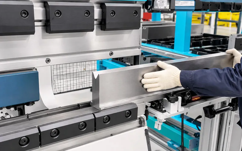
Capture the upper clamp and the installed press brake puches from the front or side, ensuring that the surrounding structure of the clamp and any visible adapters are also shown.
Start with an overall view, then provide close-up shots of the clamping contact areas as needed.
Show the following where visible:
The clamp or holder type.
The punch position inside the clamp.
Any adapter between the machine and clamp.
Adjacent components that affect loading access.
Take photos with the machine in a safe state and follow your site procedures. Do not loosen or remove tooling solely to obtain a photograph.
Suggested caption:
Photo 2. Existing upper clamp, punch interface, and any visible adapter.
Compare available press brake quick clamps with your existing holder and tooling interface
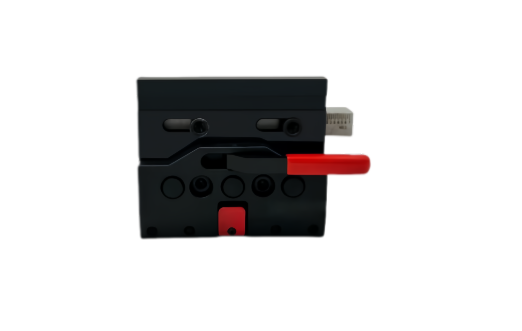
Capture images of the positioning or anti-detachment features from an angle that clearly reveals their structure. Depending on the system, these may consist of grooves, notches, pins, buttons, or other mechanisms.
If it can be done safely, please also photograph the corresponding components on the quick-clamping mechanism. Additionally, specify whether the current mold is loaded laterally or via an approved front-loading method.
Ask your supplier to confirm:
Which feature locates the punch.
Which feature is intended for retention.
Whether the existing clamp and replacement punch are compatible.
The approved loading and removal method.
Do not assume that a visible groove provides safety retention. Its function must be verified against the actual clamp and tooling design.
Suggested caption:
Photo 3. Existing punch locating or retention features and the related clamp area.
Photograph the entire punch from the side. Include the tip, overall profile, tang, and both ends of the tool.
If you use segmented tooling, arrange the segments in order and photograph the complete set. Include markings or part numbers when they are legible.
This photo helps your supplier review:
Punch shape, angle, and tip radius.
Overall tool height and segment arrangement.
Gooseneck or other clearance features.
Existing identification marks.
Add the required working length and segment quantities to your enquiry. The interface alone does not determine whether the punch suits your parts.
Suggested caption:
Photo 4. Complete punch profile and existing segment arrangement.
Use a drawing or marked sketch with clear measurement reference points. Ask your supplier which dimensions are required for your specific interface.
| Dimension or Detail | Why It Matters |
|---|---|
| Tang thickness and shape | Helps verify the fit with the existing holder |
| Locating surface positions | Helps identify how the punch is positioned in the clamp |
| Retention-feature position and geometry | Supports review of the existing retention arrangement |
| Overall punch height | Affects tool setup and available working space |
| Punch angle and tip radius | Must suit the intended bend and part geometry |
| Tool and segment lengths | Determines the required working length and segment arrangement |
| Rated load | The punch and related components must suit the bending application |
| Holder and adapter dimensions | Identifies any equipment between the machine and punch |
Record units and tolerances when available. For critical dimensions, provide a verified drawing or physical sample if requested.
Do not infer these details from the machine model alone. Existing clamps, adapters, tooling profiles, and previous modifications can change the actual interface.
Before sending your enquiry, check that you have included:
Photo 1: Punch end profile and tang.
Photo 2: Installed clamp, punch, and visible adapter.
Photo 3: Locating and retention features.
Photo 4: Complete punch profile and segment arrangement.
Machine manufacturer and model.
Clamp or holder model, if known.
Marked dimensions and an existing tooling drawing, if available.
Material, thickness, bend length, and required part drawing.
Required tool length, segment quantities, and applicable load information.
If a detail is unclear, tell your supplier which measurement or photograph is missing. Request confirmation before manufacturing begins.
The model helps narrow the enquiry, but it does not confirm the current clamp, adapter, or punch interface.
Provide photos and dimensions of the tooling actually installed.
Do not assume interchangeability from the description alone. Confirm the tang geometry, locating surfaces, retention features, dimensions, and load requirements.
Photos help identify the interface and highlight questions. Critical dimensions and application requirements still need to be verified.
A drawing or sample may be necessary for an uncertain interface.
Send MIHARTING Tooling your four photos, measured sketch, machine model, and part requirements. We can review the interface and discuss a suitable replacement or custom punch.
Request a Punch Compatibility Check
 Press Brake Sheet Follower Installation: Height and Clearance ChecklistOctober 10, 2026Before ordering a press brake sheet follower, check its installation dimensions against your machine and tooling. Accurate measurements help you identify height, clearance, and support-table conflicts before installation.view
 What Are the Differences in the Demand for Bending Machine Molds for New Energy Vehicles?June 26, 2025Compared with traditional vehicles, the demand for press brake toolings of new energy vehicles is significantly different, which is mainly reflected in the following aspects:1. Application of lightwei...view
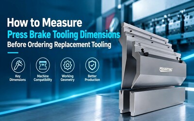 How to Measure Press Brake Tooling Dimensions Before Ordering Replacement ToolingSeptember 18, 2026Ordering replacement tooling for an older press brake is rarely as simple as identifying the machine brand and sending a photograph of the existing punch. In many fabrication shops, the original tooli...view
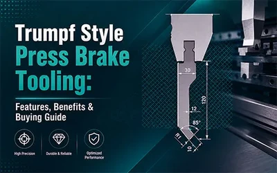 Trumpf Style Press Brake Tooling: Features, Benefits & Buying GuideAugust 27, 2026For manufacturers using high-end CNC press brakes or quick-change clamping systems, Trumpf style press brake tooling has become a preferred choice for precision bending, fast setup, and stable long-term production.view
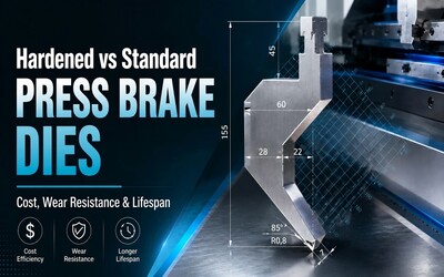 Hardened vs Standard Bystronic Press Brake Dies: Cost, Wear Resistance, and Lifespan ComparisonSeptember 14, 2026Hardened and standard Bystronic press brake dies are designed for different production requirements. Hardened dies are the preferred choice for manufacturers requiring longer tooling lifespan, improve...view
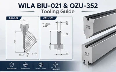 WILA BIU-021 & OZU-352 Tooling Guide: A Reliable Combination for Versatile Sheet Metal BendingJuly 6, 2026Discover why WILA BIU-021 upper tool and OZU-352 lower die are a reliable press brake tooling combination for accurate, durable, and versatile sheet metal bending.view